RIA Test Automation is a versatile software testing solution developed by RIA
Advisory to streamline and enhance the testing process for enterprise
applications. Initially created to address the challenges of efficient
regression testing in internal projects, it has now grown into a robust tool
that can adapt to any enterprise system, providing complete end-to-end testing
capabilities.
This tool especially supports various Oracle products, including Oracle
Revenue Management and Billing (ORMB), Customer-to-Meter (C2M), Utilities
Customer Cloud Service (CCS), and Meter Data Management (MDM). However, its
flexible architecture allows for seamless integration across diverse business
applications. Test Automation facilitates thorough testing across APIs, batch
processes, and user interface interactions, enabling you to deliver quality
software while minimizing the effort and costs involved in the testing
process.
Supports end-to-end test scenarios that blend API, Batch, and UI testing by enabling seamless interoperability across multiple enterprise applications and providing the capability to simulate real-world scenarios, from customer-facing interfaces to back-end processing and data handling.
Intuitive scenario chaining interface
Allows easy understanding of usage and results. Users have the ability to link various types of tests — be they API, batch, or UI — into a cohesive, end-to-end regression test. This streamlined approach removes the need for manual coordination between different tests.
Advanced assertion capabilities
Allows configurable test validation processes based on the testing needs. A new SQL assertion feature allows custom queries to extract data and a PDF validation feature to verify data accuracy in PDF files.
Pre-integrated test cases for C2M/CCS
Comes pre-integrated with C2M/CCS, delivering a suite of prebuilt test cases right out of the box. This helps you accelerate the initiation of your testing processes, effectively reducing the time to market.
Seamless CI/CD integration
Integrates into existing CI/CD pipelines through Jenkins. This enables automated triggering of test scenarios at designated stages in the development lifecycle.
Real-time dashboard for instant insights
Provides real-time updates that allow instant monitoring of test results. The dashboard serves as a centralized repository for test results, including detailed request and response payloads, screenshots, and other essential data to maintain a complete audit trail of the test execution process.
Adaptable data sampling features
Handles different types of test data, such as PDF, CSV, JSON, and database files. A new Data Sampling feature was introduced to create test data sets by pulling sample data from target databases based on IDs.
Comprehensive reports for compliance
Provides summary and detailed test reports that are downloadable. These reports can be used for audits and sign-offs, offering an extra layer of assurance and accountability.
Flexible deployment
Accommodates both cloud-based and on-premises deployment options. We employ containerization via Docker and orchestration through Kubernetes to simplify deployment and facilitate automatic scaling, offering a truly flexible and resilient testing solution.
1.2 - Quickstart Guide
Overview
When using Test Assistant, it is advisable to utilize Starter Packs for streamlined configurations and efficient implementations. However, should you opt for creating all modules from the ground up, see General configuration.
Prerequisites
Kubernetes and Helm requirements
Kubernetes version 1.28 or higher
ingress-nginx
cert-manager
PostgreSQL database with TA DB Pack
Ocular Framework (if ocular will be used as auth)
Helm version 3.0 or higher
System requirements
The following are the minimum requirements for machines running Test Assistant:
Specification
Minimum requirement
CPU
2 vCPU
Memory
8 GB
Storage
50 GB
Prerequisite packages
Test Assistant offers two prerequisite packages — Bundles and Configuration Migration Assistant (CMA). These packages serve as the foundation for Test Assistant to operate. Before installation, you are required to deploy only one of the two packages to ensure the functionality of Test Assistant. For more information, see Prerequisite packages.
Selenium IDE plugin
Selenium IDE plugin is a third-party browser plugin that needs to be installed in your browsers. This plugin is the primary tool used for scenarios involving UI recordings.
Starter packs are sets of pre-defined scenarios that you can employ for your testing projects. These scenarios cover a wide range of diverse testing situations, enabling you to begin your testing project effortlessly and efficiently. This ensures comprehensive coverage of crucial testing scenarios right from the start.
Test Assistant offers the following starter packs for the following industries:
Banking — To see the list of pre-defined scenarios for the banking industry, see Banking starter pack.
Healthcare
Utilities
Use a starter pack
Ensure that you have verified the JSON script in Postman before adding it to your Test Assistant configuration. See Verify JSON script in Postman.
Environment configuration and authentication details
Before running the test, ensure that the testing environment is properly set up and configured. This includes specifying the necessary credentials and database details for accessing the configured environment. For more information, see Create an environment in Environment.
General configuration
If you decide to customize all modules, follow these steps:
Before installation, you are required to deploy only one of the two packages to ensure the functionality of Test Assistant.
Services
The following are the services included in a pre-requisite package:
Service
Service Type
Description
TA-IWSRestCatalog
Inbound web service
Returns the catalog of REST-based web services with details based on the REST web service catalog.
TA-GetOpenAPISpec
Inbound web service
Generates the OpenAPI Specification for a given REST Inbound Web Service and version of OpenAPI Specification.
TA-GetBatcCt
Inbound web service
Retrieve batch controls configured on the extendable lookup TA-AutomationBatchControls and their corresponding value TA-ValidAutomationBatchControls.
TA-RestBatchSubmission
Inbound web service
Provides functionalities to manage and monitor batch jobs through RESTful APIs.
TA-BatchStats
Inbound web service
Returns the statistics of a batch job, including the number of records processed, the threadpool used, start time, and end time.
TA-BatchJobSubmission
Business service
Submits a batch job instance for a given batch control.
TA-CheckBatchJobStatus
Business service
Returns the status of a batch job run, such as Started, Pending, or Ended.
TA-GetBatchControl
Business service
Returns the details of a given batch control.
TA-GetBatchRunStatus
Business service
Retrieves the status and run number of a batch run for a given batch control.
TA-BatchError
Business service
Returns an error message when a batch run encounters any error.
Bundles
Test Assistant integrates with ORMB through the use of REST APIs. Components that may not be readily available in the base or framework version of ORMB can be added by importing bundles. This simplifies the integration process by removing the need to create new APIs.
On the Bundle Import popup window, input a value for the External Reference and Detailed Description fields.
Open a downloaded bundle XML file and copy the contents. Then, paste the contents to the Bundle Details field on the Bundle Import popup window.
Click Save. The Bundle Import popup window will be closed upon clicking Save.
On Main > Bundle Import > Record Actions, click Apply.
Configuration Migration Assistant (CMA)
If you have used Bundles, you do not have to use CMA. You are only required to deploy one prerequisite package.
CMA is a set of pre-defined configurations and SQL queries, such as Inbound web services, that help trigger batch executions and check the status of these executions.
Download
If you are using a TA Banking starter pack or an ORMB environment, download the files here.
If you are using a C2M environment, download the files here.
Import CMA files to your OUAF environment
Run the downloaded streamlineCMAProcess_script.sql in both the source and target environments.
Copy the created migration data export file, TA-EXPFINAL.cma, and paste it into the target environment:
If you are using ORMB 5.0, /u01/app/sploutput/ORMB5000/F1_CMA_FILES/export.
If you are using ORMB 6.0, /u01/app/sploutput/ORMB6000/F1_CMA_FILES/export.
Import the C2M_TA_C2M_Pre_Requisite.cma dataset to your target environment.
1.2.2 - Banking Starter Pack
Overview
This documentation lists all scenarios defined in the Banking starter pack. To use a starter pack, ensure that you have already completed the steps in Use a starter pack.
Customer onboarding test scenarios
Test scenarios
Available service type
Description
Create a customer
API
UI
Creates a user with the following details using API:
Customer ID number — ID number registered in the banking database.
Address — Home or work address of the user registered in the banking database.
Division — Specifies the division where the user is registered.
Create an account and contract
API
UI
Creates a bank account with the following details using API:
Account number — Account number of the user as stored in the banking database
Account type — Specifies the account type of the account number.
Account start date — Specifies when the account became active.
Contract type — Type of the contract associated with the account number.
Contract status — Describes the current status of the contract.
Contract start date — Specifies when the contract became active.
Create parent-child relationship
API
UI
Links a child's account to their parent's account.
Update customer details
API
Updates the details of a customer. The Person ID number value cannot be updated, but the following can be:
Customer identifier
Email ID
Phone number
Address line 1
Address lne 2
Address line 3
Address line 4x
City
Postal ID
Division
Update account details
API
Updates the details of an account. The Account number and Zone values cannot be updated, but the following can be:
Effective date
Char type
Char value
Bill cycle
Currency
Pricing set-up test scenarios
Test scenarios
Available service type
Description
Assign price list at a customer level
API
UI
Assigns a list of standard prices for items to a customer, including the following details:
Price List ID — Identification number of the price list where prices of items are defined.
Start date — Effective date of the price list for the customer.
End date — Specifies when the price list no longer for the customer.
Assign price list at an account level
API
UI
Assigns a list of standard prices for items to an account, including the following details:
Price List ID — Identification number of the price list where prices of items are defined.
Start date — Effective date of the price list for the customer.
End date — Specifies when the price list no longer for the customer.
Assign override pricing at a customer level
API
UI
Assigns a price list that overrides any existing price list assigned to the customer.
Assign override pricing at an account level
API
UI
Assigns a price list that overrides any existing price list assigned to an account.
Billing test scenarios
Test scenarios
Available service type
Description
Generate bill
Batch
UI
Generates a bill using the account name. For batch testing, it runs the following batches in order:
BILLOPEN (Pending Bill Generation) — Generates blank bill in pending status for accounts in given division and bill cycle for given cut off date.
BSGENREG (Bill Segment Generation) — Generates bill segments, including all billable charges, of accounts that have blank bills in an open bill cycle, input bill cycle, or division for a given cutoff date.
POSTPROC (Bill Completion) — Creates post processing bill segment that has been generated by the previous batches.
Payment test scenarios
Test scenarios
Available service type
Description
Create payment
UI
API
Creates a payment for the already generated bill.
General ledger test scenarios
Test scenarios
Available service type
Description
Link general ledger (GL) to account
Batch
Runs the following batches in order:
C1-GLASGN — Assigns the GL account to a financial transaction
GLS — Stages the GL download
GLDL — Extracts the GL download
SFTP test scenarios
Only one Service and Validation Service will be created for SFTP test executions. If you need to execute any SFTP scenario using different test data, you can create a Scenario and Data sets using the pre-defined service and validation service.
The following scenarios support file uploads for SFTP and Batch service types:
Create price list
Define price list-price item
Assign price list
Onboard a customer
Create person hierarchy
Create account
Create invoice
Upload feed management
Report generation
Available reports
Available service type
Description
Aging Detail Report
API download
SFTP download
Generates a Form of Payment (FOP) report based on aging details.
Payment Detail Report
API download
SFTP download
Generates a Form of Payment (FOP) report based on payment details.
Payment Summary Report
API download
SFTP download
Generates a Form of Payment (FOP) summary report.
Adjustment Detail Report
API download
SFTP download
Generates a Form of Payment (FOP) report with adjustment details.
1.2.3 - Healthcare Starter Pack
Overview
This documentation lists all scenarios defined in the Healthcare starter pack. To use a starter pack, ensure that you have already completed the steps in Use a starter pack.
Test scenarios
Test scenarios
Available service type
Description
Upload health product and health plan
API
Batch
Creates a health product and plan using API and processes it with batch execution.
Product code — code of the health product that will be used when creating a customer.
Plan code — code of the health plan that will be used when creating a customer.
Batch-C1-HCPHP — batch that processes the inbound messages for the creation of health products or plans.
Rate upload
API
Batch
Creates rates that define customer's charges and billable charges.
Batch-C1-HCPHP — batch that processes the inbound messages for the creation of rates.
Custmomer upload by referring rate plans
API
Batch
Updates a customer account based on product code, plan code, and rate. For example, if a rate is specified with Tobacco is Y and a customer has a YTobacco switch, then the rate will be mapped to the customer.
Runs the Batch - C1-HCEXS to process the inbound bound message for the creation of the customer, account, and contract.
Billable charge creation
Batch
Runs the following batches in order:
C1-REPC1 (Identify Entities for Repricing) — Identifies the entities that are eligible for repricing.
C1-REPC2 (Process Repricing Request) — Processes the entities captured by the C1-REPC1 batch.
C1-FIBCR (Fully Insured Billable Charge Creation) — Creates the billable charge for the processed entities.
Customer billing
Batch
UI
Generates a bill using the billable charges and account. For batch testing, it runs the following batches in order:
BILLOPEN (Pending Bill Generation) — Generates a blank bill in pending status for accounts in the specified division and bill cycle based on the given cut-off date.
BSGENREG (Bill Segment Generation) —Generates bill segments, including all billable charges, of accounts that have blank bills in an open bill cycle, input bill cycle, or division for a given cutoff date.
POSTPROC (Bill Completion) — Creates a post-processing bill segment generated by previous batches and finalizes the bill.
General ledger scenario
Batch
Runs the following batches in order:
C1-GLASGN — Assigns the General Ledger account to a financial transaction.
GLS — Stages the downloaded General Ledger.
GLDL — Extracts the downloaded General Ledger.
Create payment
API
Creates a payment for the generated bill.
2 - Dashboard
2.1 - Dashboard
Login page
To access the web application, a login page is displayed first. You must provide your credentials in the User Id and Password text fields. Clicking the Sign In button authenticates your credentials and redirects you to your Dashboard.
Dashboard
The Dashboard is the main screen you use to get an overview of the testing activities.
Live Runs
The Live Runs section displays the Run Id and provides real-time updates on running test executions.
Count Summary
The dashboard also displays the total count for Projects, Test Executions, Issues Reported, and Issued Solved.
Run Summary
The Run Summary section provides a summary of the total execution time.
By default, the summary view is filtered by Project. It lists the total number of projects, their names and displays the number of times a project has been executed. The % beside the total execution count is computed as follows:
(number of times a project has been executed/ total number of all project executions) * 100%
You can change this by selecting other options:
Feature — lists the total number of features, their names and displays the number of times a feature has been executed. The % beside the total execution count is computed as follows:
(number of times a feature has been executed/ total number of all features executions) * 100%
Status — displays the count of all projects that are either Running, Failed, or Success. The % beside the total execution count is computed as follows:
(number of <Running, Failed, or Success>/ total number of all project executions) * !00%
Tester — displays the total number of testers, their names and the number of projects each has executed. The % beside the total execution count is computed as follows:
(number of projects a tester executed/total number of all project executions) * 100%
You can also click on any section on the donut graph and view the Run Results for the selected section only.
To reset the Run Summary back to the default view, click on the reset filter icon .
Run Results
The Run Results section displays a graphical representation of the test results. The graph displays the Execution Number on the x-axis and the Scenario Count on the y-axis.
The color of the bars represents the result of the executed test scenarios. The following are the possible values:
Green — number of passing test scenarios.
Red — number of failing test scenarios.
Orange — number of pending test scenarios.
Blue — number of running test scenarios.
You can also hover on each bar to view the count summary and the project name for each execution number.
You can also use the Filter by Run ID search bar to search for your required Run ID.
By default, the graph displays the test results of the current week. You can change this by modifying the date on the calendar field.
To reset the Run Results back to the default view, click on the reset filter icon .
Recent Activities
The Recent Activities section lists all the create, update, and delete actions made in the TA web application. It displays each action in the following format:
<module> with <metadata> is <action> by <user>
<date> <time>
For example,
Project with name Sample_Test_Project_Name is Deleted by Tester1
Oct 16, 2023, 4:00 PM
You can also search for your required action by either manually typing your filter in the search bar or clicking on the icon, after which a drop down list will appear and you may choose your required filter. Multiple filters can be applied.
Filter Criteria
Description
StartAt
Start date of the executed action.
EndAt
End date of the executed action.
User
Name of the user who executed the action.
Entity
Name of the entity on which action was executed.
Issues Reported
The Issues Reported section lists all the bugs found during test execution. The issues are displayed in a tabular format with the following columns:
Column Name
Description
Type
Type of issue captured in your JIRA or Azure project.
Key
JIRA or Azure ticket logged for the issue.
Summary
Summary of the issue captured in your JIRA or Azure project.
Status
Status of the issue captured in your JIRA or Azure project.
You can also filter the list of issues by selecting a project from the dropdown list of projects associated with the configured JIRA or Azure in the Issues Tracking.
You can also select multiple filter criteria from the following list of criteria: Keys, Issue Type, Title, Label, and Status.
3 - Administration
What does your user need to understand about your project in order to use it - or potentially contribute to it?
3.1 - External Systems
Overview
An external system refers to a group of settings and configurations that are required to perform tests. A single external system can be configured to work with multiple Projects or Environments.
The External Systems module provides a centralized overview of all the configured components used for test automation. This includes information about the external system itself and details about the projects and environments it is configured to work with. From this module, you can create a new configuration or add an existing one to an external system.
To access the External Systems module, navigate to Administration > External Systems.
Create an External System
Navigate to Administration > External Systems.
Click the Create button.
Fill in the required fields.
Field
Description
Upload Logo Here
Logo of the external system.
Mandatory: No
System Name
Name of the external system.
Mandatory: Yes
External System Code
Unique identifier assigned to an external system.
The External System Code is displayed exclusively in Card View on the External Systems page.
Mandatory: Yes
Description
Describes the external system.
Mandatory: Yes
Click Save.
After creating a new external system, the system will automatically generate the following new configurations.
The card view presents all External Systems as cards, with the External System Code on the card header. The card displays the System Name and its logo. The card footer shows the count of configured items and a delete icon.
Icon
Name
Description
Projects
Displays the number of configured projects.
If you click on the icon, you will be taken to the Projects module, where you can see a list of all the configured projects in the external system.
If no project has been configured, a pop-up will appear, asking you to create a new project for the selected external system. If you click on the Yes button, you will be redirected to a page to create a new project. If you click No, you will be taken back to the External Systems view.
Environments
Displays the number of configured environments.
If you click on the icon, you will be taken to the Environments module, where you can see a list of all the configured environments in the external system.
If no environment has been configured, a pop-up will appear, asking you to create a new environment for the selected external system. If you click on Yes, you will be redirected to a page to create a new environment. If you click No, you will be taken back to the External Systems view.
Services
Displays the number of configured services.
If you click on the icon, you will be taken to the Services module, where you can see a list of all the configured services in the external system.
If no service has been configured, a pop-up will appear, asking you to create a new service for the selected external system. If you click on Yes, you will be redirected to a page to create a new service. If you click No, you will be taken back to the External Systems view.
Validation Services
Displays the number of configured validation services.
If you click on the icon, you will be taken to the Validation Services module, where you can see a list of all the configured validation services in the external system.
If no validation service has been configured, a pop-up will appear, asking you to create a new validation service for the selected external system. If you click Yes, you will be redirected to a page to create a new validation service. If you click No, you will be taken back to the External Systems view.
Steps
Displays the number of steps configured.
If you click on the icon, you will be taken to the Steps module, where you can see a list of all the configured steps in the external system.
If no validation service has been configured, a pop-up will appear, asking you to create a new step for the selected external system. If you click Yes, you will be redirected to a page to create a new step. If you click No, you will be taken back to the External Systems view.
Delete
Deletes the external sytem.
List View
The list view displays all external systems in a table format. Similar to the card view, it includes the logo, External System Name, counts of the configured items, and a icon. The description of each external system is also displayed in the list view.
The functions of the icons on the Card View are also available in the List View by clicking on the respective column value.
Filter
The card and list views include a Filter by System Name feature that allows you to filter the list of external systems by providing a keyword or the full name of the external system. Only the external systems that match the provided keyword or name will be displayed in the view.
3.1.1 - Configurations
The following configurations are only displayed for existing external systems or after creating a new one.
The following configuration tabs are not displayed when a create new external system window is displayed.
General Configurations
General configurations are configurations defining the methods in fetching services from your server for creating Services.
When an external system is created, the following general configurations are automatically created:
Load Services — used to fetch REST Catalog services.
ORMB API SPEC — used to fetch services specific to ORMB API requests.
Create a general configuration
You can also create a new general configuration by following these steps:
Navigate to Administration > External Systems.
Select an existing external system from the list.
Click General Configurations > Create.
Fill in the required fields.
Field
Description
Configuration Name
Name of the general configuration.
Mandatory: Yes
Configuration Code
Unique identifier assigned to a general configuration.
Mandatory: Yes
Configuration Value
Value of the general configuration.
Mandatory: Yes
HTTP Method
Specifies the action to be performed by the external system to your server. The following are the possible values:
POST
DELETE
GET
PATCH
PUT
Mandatory: Yes
Configuration Description
Description of the general configuration.
Mandatory: Yes
Extra Details
Defines additional details for the general configuration in key-value pairs format.
Mandatory: No
Click Save.
Modify a general configuration
To modify a general configuration, select the desired configuration, then click the Edit icon.
Batch Configurations
When an external system is created, the following batch configurations are automatically created:
Defines the configuration used to submit a batch. The Data Set is used as the request body for the POST request, and in response, a batchJobId is retrieved after a successful batch job submission. This batchJobId is used for further test execution.
See below for an example of the request body, response body, and extra details.
Ensure that you have verified the JSON script in Postman before adding it to your Test Assistant configuration. See Verify JSON script in Postman.
{"TA-BatchJobSubmission":{"batchControl":"BILLING","processDate":"2020-05-01","batchJobParameter":[{"sequence":"10","isRequired":"false","description":"Override Maximum Number of Errors","batchParameterName":"MAX-ERRORS","required":false},{"sequence":"20","isRequired":"false","description":"Division","batchParameterName":"CIS-DIVISION","required":false},{"sequence":"30","isRequired":"false","description":"Thread Pool Name","batchParameterName":"DIST-THD-POOL","required":false},{"sequence":"40","isRequired":"false","description":"Bill Cycle","batchParameterName":"BILL-CYC-CD","required":false},{"sequence":"50","isRequired":"false","batchParameterValue":"2228313882","description":"Account ID","batchParameterName":"ACCT-ID","required":false}]}}
{"TA-BatchJobSubmission":{"batchJobId":"99494498539339","batchControl":"BILLING","user":"SYSUSER","language":"ENG","batchStartDateTime":"2023-02-27T10:13:36Z","batchRunNumber":"49","batchRerunNumber":"0","threadCount":"0","batchThreadNumber":"0","processDate":"2020-05-01","maximumCommitRecords":"0","maximumTimeoutMinutes":"0","isTracingProgramStart":"false","isTracingProgramEnd":"false","isTracingSQL":"false","isTracingStandardOut":"false","description":"Billing","programName":"CIPBBILB","userInfo":"System, English","batchJobParameter":[{"sequence":"10","batchParameterName":"MAX-ERRORS","isRequired":"false","description":"Override Maximum Number of Errors"},{"sequence":"20","batchParameterName":"CIS-DIVISION","isRequired":"false","description":"Division"},{"sequence":"30","batchParameterName":"DIST-THD-POOL","isRequired":"false","description":"Thread Pool Name"},{"sequence":"40","batchParameterName":"BILL-CYC-CD","isRequired":"false","description":"Bill Cycle"},{"sequence":"50","batchParameterName":"ACCT-ID","batchParameterValue":"2228313882","isRequired":"false","description":"Account ID"}]}}
Keys
Values
jobIdPath
$.TA-BatchJobSubmission.batchJobId
batchControl
$.TA-BatchJobSubmission.batchControl
batchRunNumber
$.TA-BatchJobSubmission.batchRunNumber
Job Status URL
Defines the configuration used to get the status of a submitted batch. The batchJobId from Job Submission URL configuration is used to retrieve a response on whether the batch job status ran successfully.
The nodes in this configuration are used to store the following batch run information:
batchJobStatus — status of the batch run. The possible values are ST, IP, PD, or ED.
throttleTime — number of minutes the batch run is in a PD or IP state before it automatically stops.
batchJobId
batchRunNumber
See below for an example of the request body, response body, and extra details.
Ensure that you have verified the JSON script in Postman before adding it to your Test Assistant configuration. See Verify JSON script in Postman.
Defines the configuration used to get the overall statistics of the submitted batch. The statistics can either be completed or error. If it is error, the TotalError node will have a value that will be used in the next service to get the error details. The batchRunNumber from Job Status URL and the batchNbr from Job Error URL are used in the POST request to get the following nodes in the Response Body.
See below for an example of the request body, response body, and extra details.
Ensure that you have verified the JSON script in Postman before adding it to your Test Assistant configuration. See Verify JSON script in Postman.
Unique identifier assigned to a batch configuration.
Mandatory: Yes
Configuration Value
Value of the batch configuration.
Mandatory: Yes
HTTP Method
Specifies the action to be performed by the external system to your server. The following are the possible values:
POST
DELETE
GET
PATCH
PUT
Mandatory: Yes
Configuration Description
Description of the batch configuration.
Mandatory: Yes
Request and Response Body
Defines the template for the request and response bodies.
Mandatory: No
Extra Details
Defines additional details for the batch configuration in key-value pairs format.
Mandatory: No
Modify a batch configuration
To modify a batch configuration, select the desired configuration, then click the Edit icon.
Ensure that you have verified the JSON script in Postman before adding it to your Test Assistant configuration. See Verify JSON script in Postman.
Error Configurations
Error configurations show customized error messages after test executions on the Run Results screen.
Create an error configuration
Navigate to Administration > External Systems.
Select an existing external system from the list.
Click Error Configurations > Create.
Field
Description
Configuration Name
Name of the error configuration.
Mandatory: Yes
Configuration Description
Description of the error configuration.
Mandatory: Yes
Configuration Path
Automatically gets the value of the JSON Path textbox in the Structure of Error Body configuration, when Select is clicked.
Mandatory: Yes
Structure of Error Body
Response value for failed results.
For example:
{
  "problemDetailDocument": {
    "problemType": "https://ec2-54-225-50-201.compute-1.amazonaws.com:7002/ouaf/rest/ouaf/message/3/253",
    "title": "Person ID field missing",
    "httpStatus": 400,
    "detail": "A mandatory field has been left blank. Please enter a value and retry your request.",
    "problemInstance": "https://ec2-54-225-50-201.compute-1.amazonaws.com:7002/ouaf/rest/ouaf/errorMessageInstance/20230612064333021/SYSUSER/3/253?request=%2Fouaf%2Frest%2Fouaf%2Fapi%2Fiws%2FTA-CreateAccount%2FaddAccount&method=POST",
    "serverMessage": {
      "messageCategory": 3,
      "messageNbr": 253,
      "callSequence": ";CIPCACPR;CIPCACPL;CIPCACCP",
      "programName": "CIPCACPR",
      "messageText": "Person ID field missing",
      "longDescription": "A mandatory field has been left blank. Please enter a value and retry your request.",
      "tableName": "CI_ACCT_PER",
      "fieldName": "PER_ID"
    }
  }
}
Mandatory: Yes
6. Click Save.
Modify an error configuration
To modify an error configuration, select the desired configuration, then click the Edit icon.
Global Variable Configurations
The variable configured in the Global Variable Configurations module can be used across the external systems. Global variables are used to hide actual values. A global variable will be displayed instead of its table actual parameter value. For example, you can set a global variable for your username and password so that their actual values will not be displayed on test execution and results.
You can use global variables in the Steps and Data Sets modules.
Create a global variable configuration
Navigate to Administration > External Systems.
Select an existing external system from the list.
Click Global Variable Configurations > Create.
Modify a global variable configuration
To modify a global variable configuration, select the desired configuration, then click the Edit icon.
3.2 - Environments
Overview
A testing environment can be a development, staging, production, or any other project-specific environment. The Environments module manages your testing environments. This module allows you to add, modify, or delete environments according to your needs.
Multiple environments can be configured for a single External System.
To access the Environments module, navigate to Administration > Environments.
Create an environment
Ensure that you have already created your external system before creating an environment.
The following are the different ways to create a new environment:
In the External Systems view, if your system has no environments configured, click on the card view or on the 0 environment column value in the list view. This option will automatically connect the environment to your selected external system.
When viewing an existing external system, navigate to the External Systems tab and click Add New Environment. This option will automatically connect the created environment to your selected external system.
In Administration > Environments, click Create. This option will have a Select External System dropdown list that requires you to select an existing external system.
Field
Description
External System Name
Name of the external system that will use the environment.
When creating an environment from an external system, this field is automatically populated with the initially selected external system. Otherwise, a dropdown list of all available external systems is displayed.
Mandatory: Yes
Environment Name
Name of the environment.
Mandatory: Yes
Environment Description
Description of the environment.
Mandatory: Yes
API Base URL
URL of the environment for API or Batch testing.
Mandatory: Yes
Application URL
URL of the environment for UI testing.
You can also specify the target URL in the Service > Uploaded File > url field. In case, different target URLs are specified in the Application URL and Uploaded File > url fields, the system will use the URL specified in the Application URL.
Mandatory: No
Default
Sets the selected environment as default for test runs and templates of an external system.
Mandatory: Yes
Skip Login
Allows test execution in the environment without authentication.
Mandatory: No
Proxy Enabled
Enables the proxy server for the environment. You should provide the following mandatory fields:
Proxy Address — Address of the proxy server.
Proxy Port — Port of the proxy server.
Mandatory: No
SFTP
Enables the Secure File Transfer Protocol(SFTP) to download and upload files from any server. You should provide the following mandatory fields:
Server Address — Address of the SFTP server.
Port — Port of the SFTP server.
Username — Username used to log in to the STFP server.
Password — Password used to log in to the STFP server.
Mandatory: No
Auth Details
Specifies the authentication details for the test environment. The following are the possible values:
Parameters used to connect to a database. For more information, see Database Details.
Mandatory: No
Authentication Details
The following are the supported authentications for your environment and the additional mandatory settings that you need to provide.
Authentication
Mandatory Fields
BASIC
If you select BASIC authentication, you need to supply the following:
Username — Username to use when connecting to the target test environment.
Password — Password to use when connecting to the target test environment.
ORMB
If you select ORMB authentication, you need to supply the following:
Username — Username to use when connecting to your ORMB environment.
Password — Username to use when connecting to your ORMB environment.
API_KEY
If you select API_KEY authentication, you need to supply the following:
Key — API key to access the API service.
Value — Actual value of the specified API Key.
Add To — Defines how and where the API Key should be added to the API service.
TOKEN
If you select TOKEN authentication, you need to supply the following:
Token — Value of the token to access an application or an API service.
SIGNATURE
If you select SIGNATURE authentication, you need to supply the following:
Access Key — Authorization key to access your account or application.
Secret Key — Password of the Access Key.
OCULAR
If you select OCULAR authentication, you need to supply the following:
Username — Username to use when connecting to your EPM.
Password — Password to use when connecting to your EPM.
Database Details
Field
Description
Name
Name of the database to connect to.
Type
Type of the database. The possible values are the following:
POSTGRES
ORACLE
Username
Username you use to connect to your database.
Password
Password you use to connect to your database.
URL
URL of the database to connect to.
Views
Card View
The card view presents all Environments in the form of cards, with the Environment Code on the card header. The card displays the Environment Name, External System Name, and the configured authentication type. The card footer shows a delete icon.
Clicking on the External System Name will redirect you to view the external system details. Clicking on any part of the card except the External System Name and the delete icon will display the environment details.
List View
The list view displays all Environments in a table format. Similar to the card view, it includes the Environment Name, the configured authentication type, and a delete icon. Additionally, the description of each environment is also displayed in the list view.
Column Name
Description
Default
Indicates whether the environment is the default for the configured external system.
Environment Name
Name of the environment.
When clicked, the environment details are displayed.
Description
Description of the environment.
When clicked, the environment details are displayed.
Auth Type
Authentication type configured for the environment.
When clicked, the environment details are displayed.
External System
Code of the external system configured to use the environment.
When clicked, the external system details are displayed.
Actions
Displays that allows you to remove the selected environment.
Filter
The following filters are available on both card and list views:
Filter by Environment Name — allows you to filter the list of environments by providing a keyword or the full name of the environment. Only the environments that match the provided keyword or name will be displayed in the view.
Filter By External System Name — allows you to filter the list of environments with the associated external system by providing a keyword or the full name of the external system. Click on the to open the Filter Criteria for External System Name. Only the environment with a configured external system that matches the provided keyword or name will be displayed in the view.
3.3 - Services
Overview
The Services module manages the individual units of a Scenario.
To access the Services module, navigate to Administration > Services.
Create a service
The following are the different ways to create a new service:
In the External Systems view, if your system has no environments configured, click on the card view or on the 0 service column value in the list view. This option will automatically connect the service to your selected external system.
In Administration > Services, click Create. This option will have a Select External System dropdown list that requires you to select an existing external system.
Field
Description
Select External System
Name of the external system that will use the service.
When creating a service from an external system, this field is automatically populated with the initially selected external system. Otherwise, a dropdown list of all available external systems is displayed.
Specifies the type of service. The following are the possible values:
API
Batch
UI
SFTP
When creating a UI service type, additional configurations are displayed. See UI service type.
Mandatory: Yes
Service Method
If you chose API service type, this additional configuration is displayed.
Specifies the action to be performed by the external system to your server. The following are the possible values:
POST
DELETE
GET
PATCH
PUT
Mandatory: Yes
Service URL
URL of the API.
Mandatory: Yes
Payload Details
Specified the payload details of the service. You can choose between the following formats:
Form Data — allows you to define key-value pairs.
JSON — allows you to define the template of the request and response bodies.
Ensure that you have verified the JSON script in Postman before adding it to your Test Assistant configuration. See Verify JSON script in Postman.
Mandatory: No
Load an existing Inbound Web Service
If you want to test an Inbound Web Service, you can use an existing service that is already associated with an external system. To load an existing service, follow these steps:
In the Administration > Services, click Create.
Click on the Select External System dropdown list.
Select your external system. After selecting an external system, the Load Services button will be enabled.
Enter your API URL.
Click Load Services.
On clicking the Load Services button, a Swagger Services popup window will appear listing all the available services, click to download your needed system service.
After selecting the service, the Basic Details and Payload Details tabs are automatically filled out. Verify that this is all the information that you need.
Enter a description for your service in the Service Description text field.
Click Save.
UI service type
When creating a UI service type, it is recommended that you verify the steps manually and execute a Selenium IDE recording first.
When you chose UI service type, the following additional configuration tabs are displayed. The configurations can also be downloaded by clicking the on the Payload Details header.
Configuration tab
Description
Screenshot Capture
Specifies the commands in which, when performed, a screenshot is automatically captured.
Selected Commands
Specifies the commands you want to add in the Request Body.
All selected click commands will be added as a Data set for UI test executions.
Upload File
Uploads the file you wish to use for the UI service type.
Views
Card view
The card view presents all Services in the form of cards.
Card Element
Description
Service Code
Code of the service that is displayed on the card header.
When clicked, the service details are displayed.
Service Name
Name of the service.
When clicked, the service details are displayed.
External System Name
Name of the external system configured for the service.
When clicked, the external system details are displayed.
Service Type
Type of the service.
When clicked, the service details are displayed.
Service Method
HTTP method to be used by the service.
Template icon that displayed the template for request and response bodies when clicked.
Delete icon that allows you to delete the selected service.
List view
The list view displays all services in a tabular format.
Column Name
Description
Method
Indicates the HTTP method configured for the service.
When clicked, the service details are displayed.
Name
Name and type of the service.
The colored dots before the service name indicate the type.
When clicked, the service details are displayed.
Description
Description of the service.
When clicked, the service details are displayed.
External System
Code of the external system configured in the service.
When clicked, the external system details are displayed.
URL
Service URL where the HTTP method will be executed.
When clicked, the service details are displayed.
Templates
Displays a template icon.
When clicked, the template for the request and response bodies is displayed.
Actions
Displays that allows you to delete the selected service.
Filter
The following filters are available on both card and list views:
Filter by Service Name — allows you to filter the list of services by providing a keyword or the full name of the service. Only the services that match the provided keyword or name will be displayed in the view.
Filter By External System Name — allows you to filter the list of services with the associated external system by providing a keyword or the full name of the external system. Click on the to open the Filter Criteria for External System Name. Only the service with a configured external system that matches the provided keyword or name will be displayed in the view.
3.4 - Validation Services
Overview
The Validation Services module serves as a quality control mechanism ensuring the completeness and correctness of data, information, or functionality provided are used to validate Services.
To access the Environment module, navigate to Administration > Validation Services.
Create a validation service
The following are the different ways to create a new validation service:
In the External Systems view, if your system has no validation service configured, click on the card view or on the 0 validation service column value in the list view. This option will automatically connect the service to your selected external system.
In Administration > Validation Services, click Create. This option will have a Select External System dropdown list that requires you to select an existing external system.
Field
Description
Select External System
Name of the external system that will use the validation service.
When creating a validation service from an external system, this field is automatically populated with the initially selected external system. Otherwise, a dropdown list of all available external systems is displayed.
Mandatory: Yes
Validation Service Name
Name of the validation service.
Mandatory: Yes
Service Type
Specifies the type of validation service. The following are the possible values:
API
File
Query
Mandatory: Yes
Validation Service Description
Description of the validation service.
Mandatory: Yes
API service type
If you choose an API service type, you must configure the following mandatory fields.
Field
Description
Http method
Specifies the action to be performed by the validation service to your server. The following are the possible values:
POST
DELETE
GET
PATCH
PUT
Mandatory: Yes
Validation Service URL
API URL used for the validation.
Mandatory: Yes
Payload Details > Request Body
Template of the request body.
Ensure that you have verified the JSON script in Postman before adding it to your Test Assistant configuration. See Verify JSON script in Postman.
On Validation Service > Payload Details > Validation Service Definition tab, a Configure button is available to configure the following:
Validation Service Input — Specifies the services that provide input to the validation service.
Validation Service Expected Results — Specifies the services that are expected and will be validated.
To configure a validation service input or a validation service expected results, follow these steps:
Click Select Field.
In the Json Path Selector, expand the JSON format of the specified Request Body.
Click on the field you want to configure as input or expected result. The Json Path text field will automatically be populated with the JSON path of the selected field.
Click Select.
The selected JSON path in Step 3 is automatically listed in Selected Service.
Click Done.
To delete a configured validation service input or expected result, click beside the service you want to delete.
File service type
If you choose a File service type, you must configure the following mandatory fields.
Field
Description
File Type
Specifies the action to be performed by the validation service to your server. The following are the possible values:
PDF
TXT
JSON
XLSX
HTML
Mandatory: Yes
Upload File
Uploads the file containing the expected fields for validation.
The Payload Details section provides you with an overview of the uploaded file and the Keys that were automatically identified within it. You can also choose specific keys for validation purposes by selecting the Select checkbox next to the key.
Query service type
If you choose a Query service type, you must configure the following mandatory fields.
Field
Description
Select Database
Database where the query service will run.
Ensure that you have added your preferred database in the Environments module. For more information, see Database Details.
Query
Actual query to run and get results for validation. This can contain dynamic parameters using the ${parameterName} format.
Expected Fields
List of expected fields extracted from the provided Query.
This is automatically filled out when the Extract Filters is clicked.
You can also specify the Field Label for a field by clicking on the in the Actions column.
Input Fields
List of input fields extracted from the provided Query.
This is automatically filled out when the Extract Filters is clicked.
You can also specify the Field Label for a field by clicking on the in the Actions column.
Views
Card view
The card view displays all validation services as cards.
Card Element
Description
Validation Service Code
Code of the validation service that is displayed on the card header.
When clicked, the validation service details are displayed.
Validation Service Name
Name of the validation service.
When clicked, the validation service details are displayed.
External System Name
Name of the external system configured for the validation service.
When clicked, the external system details are displayed.
Validation Service Type
Type of the validation service.
When clicked, the validation service details are displayed.
Template icon that allows you to view the request and response body templates.
Delete icon that allows you to delete the selected validation service.
List view
The list view displays all validation services in a tabular format.
Column Name
Description
Validation Service Name
Name and type of the validation service.
The colored dots before the validation service name indicate the type.
When clicked, the validation service details are displayed.
Type
Type of the validation service.
When clicked, the validation service details are displayed.
Description
Description of the validation service.
When clicked, the validation service details are displayed.
External System
Code of the external system configured in the service.
When clicked, the external system details are displayed.
Components
Displays that allows you to view the request and response body templates.
Actions
Displaysthat allows you to delete the selected validation service.
Filter
The following filters are available on both card and list views:
Filter by Validation Service Name — allows you to filter the list of validation services by providing a keyword or the full name of the validation service. Only the validation services that match the provided keyword or name will be displayed in the view.
Filter By External System Name — allows you to filter the list of validation services with the associated external system by providing a keyword or the full name of the external system. Click on the to open the Filter Criteria for External System Name. Only the validation service with a configured external system that matches the provided keyword or name will be displayed in the view.
Multiple steps can be associated with one Service only if the steps have similar endpoint URLs and different node values. You can also associate a Validation Service with a Step.
To access the Steps module, navigate to Administration > Steps.
Create a step
The following are the different ways to create a new step:
In the External Systems view, if your system has no environments configured, click on the card view or on the 0 service column value in the list view. This option will automatically connect the step to your selected external system.
In Administration > Steps, click Create. This option will have a Select External System dropdown list that requires you to select an existing external system.
Field
Description
Select External System
Name of the external system that will use the environment.
When creating a step from an external system, this field is automatically populated with the initially selected external system. Otherwise, a dropdown list of all available external systems is displayed.
Mandatory: Yes
Step Name
Name of the step.
Mandatory: Yes
Step Description
Description of the service.
Mandatory: Yes
Step Type
Specifies the type of step. The following are the possible values:
API — ensure that you have configured a Service with a API type. Otherwise, an error message is displayed.
Batch — ensure that you have configured the Batch Configurations of your external system. When you choose this step type, a Batch Name field is displayed. This field is optional.
UI — ensure that you have configured a Service with a UI type. Otherwise, an error message is displayed.
SFTP — ensure that you have configured a Service with a SFTP type. When you choose this step type, you have to select one between the Download File and Upload File operations.
Mandatory: Yes
Select Service
Displays a dropdown list of services with the same type as the configured Step Type and associated with the selected external system.
Mandatory: Yes
Select Validation Service
Displays a dropdown list of all validation services associated with the configured external system.
Mandatory: No
Navigation URL
Specifies the URL to navigate to after the execution of the step.
A BPA script is required when testing an ORMB or CR2M application.
Mandatory: No
Add Global Variable
Enables you to assign a variable name to specific fields of the request body. See Add a global variable.
Mandatory: No
Request Body
According to selected service name, request body gets displayed. If user has entered Path parameters, Query parameters, Headers in the service that also get display while creating step.
Add a global variable
Field
Description
Select Configured Variable
When ticked, the list will show only those fields that have configured variables.
Filter By Name
Allows you to filter the list by the Field Name.
Field Name
Displays a list of fields available in your request body that can be assigned with a variable.
Variable
Displays the variable assigned to the field.
When the is clicked, this column is enabled for updating. You can either do the following:
Select from the list of all available global variables configured in the Global Variable configurations of your initially selected external system.
Add a new global variable that is automatically added to the Global Variable configurations of your initially selected external system.
Actions
Displays that, when clicked, will do the following:
Enables the Variable column for updating.
Displays that, when clicked, saves your changes, and that cancels your changes.
Views
Card view
The card view displays all steps as cards.
Card Element
Description
Step Code
Code of the step that is displayed on the card header.
When clicked, the step details are displayed.
Step Name
Name of the validation service.
When clicked, the step details are displayed.
Service Name
Name of the external system configured for the validation service.
When clicked, the service details are displayed.
Templates icon that displays the configured template for the selected step.
Delete icon that allows you to delete the selected step.
List view
The list view displays all steps in a tabular format.
Column Name
Description
Step Name
Name of the step.
When clicked, the step details are displayed.
Description
Description of the step.
When clicked, the step details are displayed.
Service Name
Name of the service configured to use the step.
When clicked, the service details are displayed.
Type
Type of the service configured to use the step.
When clicked, the step details are displayed.
Data Template
Displays that displays the configured template for the selected step.
Actions
Displays that allows you to delete the selected step.
Filter
The following filters are available on both card and list views:
Filter by Steps Name — allows you to filter the list of steps by providing a keyword or the full name of the step. Only the steps that match the provided keyword or name will be displayed in the view.
Filter By External System Name — allows you to filter the list of steps with the associated external system by providing a keyword or the full name of the external system. Click on the to open the Filter Criteria for External System Name. Only the step with a configured external system that matches the provided keyword or name will be displayed in the view.
4 - Test Suites
4.1 - Projects
Overview
The Projects module enables you to create a personalized testing workspace to avoid overlap in your activities. Depending on your testing requirements, you can customize your workspace by adding items such as External System, Features, and Scenarios.
To access the Projects module, navigate to Test Suites > Projects.
Create a project
The following are the different ways to create a new environment:
In the External Systems view, if your system has no projects configured, click on the card view or on the 0 environment column value in the list view. This option will automatically connect the environment to your selected external system.
In Test Suites > Projects, click Create. This option will have an Add External System dropdown list that requires you to select an existing external system.
Field
Description
Logo
Logo of the project, if available. The supported file types are png/jpg/jpeg.
Mandatory: No
Project Name
Name of the project.
Mandatory: Yes
Project Code
Unique identifier assigned to a project.
The Project Code is displayed exclusively in Card View on the Projects page.
Mandatory: Yes
Project Description
Description of the project.
Mandatory: Yes
Add External System
Name of the external system that will use the environment.
When creating an environment from an external system, this field is automatically populated with the initially selected external system. Otherwise, a dropdown list of all available external systems is displayed.
Mandatory: Yes
Views
Card view
The card view presents all Services in the form of cards.
Card Element
Description
Project Code
Code of the project that is displayed on the card header.
When clicked, the service details are displayed.
Project Name
Name of the project.
When clicked, the service details are displayed.
External System Name
Code of the external systems configured for the project.
When an external system code is clicked, the external system details are displayed.
Logo
Logo of the project, if available.
When clicked, the service details are displayed.
Displays the total number of features associated with the project.
When clicked, all the features associated with the project are displayed as cards. If no features configured, you will be asked to create a new scenario.
Displays the total number of scenarios associated with the project.
When clicked, all the scenarios associated with the project are displayed as cards. If no scenarios configured, you will be asked to create a new scenario.
Clones the selected project.
When clicked, a popup window is displayed asking you to provide a new Project Name and Project Code. All other components of the selected project are copied.
Delete icon that allows you to delete the selected project.
List view
The list view displays all projects in a tabular format.
Column Name
Description
Logo
Logo of the project.
When clicked, the project details are displayed.
Project Code
Name and code of the project.
When clicked, the project details are displayed.
Description
Description of the project.
When clicked, the project details are displayed.
External System Count
Total number of external systems configured in the project.
When clicked, all the external systems configured in the project are displayed as cards.
Features Count
Total number of features associated with the project.
When clicked, all the features associated with the project are displayed as cards. If no features configured, you will be asked to create a new scenario.
Scenarios Count
Total number of scenarios associated with the project.
When clicked, all the scenarios associated with the project are displayed as cards. If no scenarios are configured, you will be asked to create a new scenario.
Actions
Displays the following icons:
— Clone icon that allows you to clone the selected project. When clicked, a popup window is displayed asking you to provide a new Project Name and Project Code. All other components of the selected project are copied.
— Delete icon that allows you to delete the selected project.
Filter
Both the card and list views include a Filter by Project Name feature that allows you to filter the list of projects by providing a keyword or the full name of the project. Only the projects that match the provided keyword or name will be displayed in the view.
4.2 - Features
Overview
To access the Features module, navigate to Test Suites > Features.
Create a feature
The following are the different ways to create a new feature:
In the Projects view, if your project has no features configured, click on the card view or on the 0Features Count column value in the list view. This option will automatically connect the feature to your project.
In Test Suites > Features, click Create. This option will have a Select Project dropdown list that requires you to select an existing project.
Field
Description
Select Project
Name of the project that will use the feature.
When creating a feature from a project, this field is automatically populated with the initially selected project. Otherwise, a dropdown list of all available projects is displayed.
Mandatory: Yes
Feature Name
Name of the feature.
Mandatory: Yes
Feature Code
Unique identifier assigned to a feature.
The Feature Code is displayed exclusively in Card View on the Features page.
Mandatory: Yes
Feature Description
Description of the feature.
Mandatory: Yes
Views
Card view
The card view presents all Features in the form of cards.
Card Element
Description
Feature Code
Code of the feature that is displayed on the card header.
When clicked, the feature details are displayed.
Feature Name
Name of the project.
When clicked, the service details are displayed.
Project Name
Code of the external systems configured for the project.
When an external system code is clicked, the external system details are displayed.
Displays the total number of scenarios associated with the feature.
When clicked, all the scenarios associated with the project are displayed as cards. If no scenarios are configured, you will be asked to create a new scenario.
Clones the selected feature.
When clicked, a popup window is displayed asking you to provide a new Feature Name and Feature Code. All other components of the selected feature are copied.
Delete icon that allows you to delete the selected feature.
List view
The list view displays all features in a tabular format.
Column Name
Description
Feature Name
Name and code of the feature.
When clicked, the feature details are displayed.
Description
Description of the feature.
When clicked, the feature details are displayed.
Project Code
Code of the project associated with the feature.
When clicked, the project details are displayed.
Displays the total number of scenarios associated with the project.
When clicked, all the scenarios associated with the feature are displayed as cards. If no scenarios are configured, you will be asked to create a new scenario.
Actions
Displays the following icons:
— Clone icon that allows you to clone the selected feature. When clicked, a popup window is displayed asking you to provide a new Feature Name and Feature Code. All other components of the selected feature are copied.
— Delete icon that allows you to delete the selected feature.
Filter
The following filters are available on both card and list views:
Filter by Feature Name — allows you to filter the list of features by providing a keyword or the full name of the feature. Only the features that match the provided keyword or name will be displayed in the view. To filter by feature name, input the required keyword or name in the filter text box.
Filter By Project — allows you to filter the list of features with the configured project by providing a keyword or the full name of the project. Only the features with a configured project that matches the provided keyword or name will be displayed in the view.
4.3 - Scenarios
Overview
By clicking on Test Suites -> Scenarios, the user is taken to the Scenarios screen.
Create a scenario
The following are the different ways to create a new scenario:
In the Projects view, if your project has no scenarios configured, click on the card view or on the 0Scenarios Count column value in the list view. This option will automatically connect the scenario to your project.
In the Features view, if your feature has no scenarios configured, click on the card view or on the 0 feature count column value in the list view. This option will automatically connect the scenario to your feature and to the project associated with the selected feature.
In Test Suites > Scenarios, click Create. This option will have a Select Project dropdown list that requires you to select an existing project.
Field Name
Description
Select Project
Name of the project that will use the scenario.
Ensure that your project has a configured feature. Otherwise, an error message is displayed.
When creating a scenario from a project, this field is automatically populated with the initially selected project. Otherwise, a dropdown list of all available projects is displayed.
Mandatory: Yes
Select External System
Name of the external system where the scenario will be executed.
Displays a dropdown list of all the external systems associated with the project.
Mandatory: Yes
Select Feature
Name of the feature that will use the scenario.
When creating a scenario from a feature, the Select Feature and Select Project fields are automatically populated with the initially selected feature and its associated project. Otherwise, a dropdown list of all available features associated with the initially selected project is displayed.
Mandatory: Yes
Scenario Name
Name of the scenario.
Mandatory: Yes
Scenario Description
Description of the scenario.
Mandatory: Yes
Step Type
Specifies the type of step. The following are the possible values:
API
Batch
UI
SFTP
Query
Ensure that you have configured the steps that match your selected types.
Select Steps
Displays a dropdown list of steps configured for the selected external system and matching the selected type.
Steps
Lists all the selected steps for the scenario.
Each step is displayed as a tile with the Step Name, Step Description, Validation Service, Step typ.
You can drag and drop the step tiles to change the order of execution.
Step > Wait in Sec
Number of seconds before proceeding to the next configured step or ending the scenario execution.
Step >
Deletes the step.
Step > Validation Service
Displays a dropdown list of all validation services configured with the step.
Dataset from Query
If you plan to use a dataset from a query for a scenario, you have to configure this tab.
Field
Description
Select Environment
Dropdown list displaying all the available environments for the selected external system in the Scenario Details tab.
Select Database
Dropdown list displaying all the available databases for the selected environment.
Query
Defines the query to be executed in the database to generate a dataset.
Note: When writing the query for the mining functionality, ensure that the data returned from the first column of the query should be unique for each row of data returned. The value from the first column is appended to the dataset names to make them unique. Failure to do so will result in a unique key constraint error.
Filters
Automatically list all dynamic parameters written in ${parameterName} format from the Query.
Extract Columns
Extracts the output columns from the Query.
Velocity Details
Displays the Output Columns generated after clicking the Extract Columns. It also displays the templates of the steps selected in the Scenario Details tab.
See below for a sample Velocity Script Details.
Sequence and Linking
Sequencing
To organize the order in which your scenarios are executed, you can filter the list of scenarios by the feature name and rearrange their sequence by dragging and dropping. The sequence in which the scenarios are executed is indicated by the number in the Sequence column. Similarly, you can also arrange the order of steps within a scenario by dragging and dropping them into the desired sequence.
Scenarios Linking
You can link scenarios to pass parameters from one scenario to another. However, you can only link scenarios associated with the same feature.
To link scenarios, follow these steps:
Filter your scenarios by feature name. This will display all scenarios associated with a feature. You can also filter the list more by adding another filter by scenario name. For more information on filters, see Filter.
Click on Sequence and Linking.
Click on the Scenario Linking icon of the scenario you wish to receive a parameter.
A popup window is displayed. Click Create New to add a row.\
Choose a Source Scenario. All scenarios under the specified feature are displayed.
Choose a Source Step. All steps associated with the selected scenario in the previous step are displayed.
Choose a Target Step. All steps associated with the selected scenario in Step 3 are displayed.
Click the icon in the Source Link column.
Click Create New.
Click select source Link. The Json Path Selector is automatically populated with available parameters.
Click on the parameter that you want to set as the source. The Json Path textbox is automatically updated. Click on the parameter that you want to set as the source. The Json Path textbox is automatically updated.
Click Select. The chosen parameter is added to the PrioritySource Link list.
Click Done. The chosen parameter is displayed in the Source Link column.
Click the icon in the Target Link column.
Choose the target parameter from the list of available parameters.
Click Select. The chosen parameter is displayed in the Target Link column.
Click to save.
The scenario linking count is updated.
Steps Linking
You can link steps to pass parameters from one step to another. However, you can only link steps associated with the same scenario.
To link scenarios, follow these steps:
Filter your scenarios by feature name. This will display all scenarios associated with a feature. You can also filter the list more by adding another filter by scenario name. For more information on filters, see Filter.
Select a scenario. The steps associated with the selected scenario are displayed in the right table.
Click the Step Linking icon.
A popup window is displayed. Click Create New to add a row.
Select a Source Step. Only the steps associated with the selected scenario are displayed.
Click the icon in the Source Link column.
Click Create New.
Click select source Link. The Json Path Selector is automatically populated with available parameters.
Click on the parameter that you want to set as the source. The Json Path textbox is automatically updated. Click on the parameter that you want to set as the source. The Json Path textbox is automatically updated.\
Click Select. The chosen parameter is added to the PrioritySource Link list.\
Click Done. The chosen parameter is displayed in the Source Link column.
Click the icon in the Target Link column.
Choose the target parameter from the list of available parameters.
Click Select. The chosen parameter is added to the Target Link column.
Click to save.
The step linking count is updated.
Views
Card view
The card view presents all scenarios in the form of cards.
Card Element
Description
Scenario Name
Name of the scenario.
When clicked, the scenario details are displayed.
Feature Name
Name of the feature associated with the scenario.
When clicked, the feature details are displayed.
Sequence
Displays the sequence number of the scenario.
When clicked, the scenario details are displayed.
Displays the combined request body templates of all the added steps. You can view the template in JSON or Excel format.
Downloads the combined request body templates of all the added steps. You can download the template in JSON or CSV format.
Displays the total number of datasets associated with the scenario. When clicked, all the datasets associated with the scenario are displayed as cards. If no dataset is configured, you will be asked to create a new dataset.
Displays the project details.
Steps
Displays all the step types and the number of steps of each type configured in the scenario.
When clicked, the scenario details are displayed.
Clone icon that allows you to clone the selected scenario. When clicked, a popup window is displayed asking you to provide a new Scenario Name. All other components of the selected scenario are copied.
Delete icon that allows you to delete the selected scenario.
List view
The list view displays all scenarios in a tabular format.
Column Name
Description
Sequence
Displays the sequence number of the scenario.
When clicked, the scenario details are displayed.
Scenario Name
Name of the scenario.
When clicked, the scenario details are displayed.
Description
Description of the scenario.
When clicked, the scenario details are displayed.
Project Code
Code of the project associated with the scenario.
When clicked, the project details are displayed.
Feature
Name of the feature associated with the scenario.
When clicked, the feature details are displayed.
Steps
Displays all the step types and the number of steps of each type configured in the scenario.
When clicked, the scenario details are displayed.
Scenario Links
Number of scenarios linked to the selected scenario.
Data Sets
Displays the following icons:
— Displays the combined request body templates of all the added steps. You can view the template in JSON or Excel format.
— Downloads the combined request body templates of all the added steps. You can download the template in JSON or CSV format.
— Displays the total number of datasets associated with the scenario. When clicked, all the datasets associated with the scenario are displayed as cards. If no dataset is configured, you will be asked to create a new dataset.
Actions
Displays the following icons:
— Clone icon that allows you to clone the selected scenario. When clicked, a popup window is displayed asking you to provide a new Scenario Name. All other components of the selected scenario are copied.
— Delete icon that allows you to delete the selected scenario.
Filter
Multiple of the following filters can be selected on both card and list views:
Filter By Scenario Name — allows you to filter the list of scenarios with the configured project by providing a keyword or the full name of the scenario. Only the scenarios that match the provided keyword or name will be displayed in the view. The filter value can be added in the initial search box which comes up. No filter criteria has to be selected.
Filter By Step Type— allows you to filter the list of scenarios with the configured step type by providing the full name of the step type. Only the scenarios with a configured step that matches the provided name will be displayed in the view. Step Type filter criteria has to be selected.
Filter By Feature Name — allows you to filter the list of scenarios with the configured feature by providing a keyword or the full name of the feature. Only the scenarios with a configured feature that matches the provided keyword or name will be displayed in the view. Feature Name filter criteria has to be selected.
Filter By Project Code — allows you to filter the list of scenarios with the configured project code by providing a keyword or the full name of the code. Only the scenarios that match the provided keyword or name will be displayed in the view. Project Code filter criteria has to be selected.
4.4 - Data Sets
Overview
The Data Sets module allows you to manage your test data, including viewing available datasets, creating new ones from templates or queries, and cloning existing datasets.
To access the Data Sets module, navigate to Test Suites > Data Sets.
Create a data set
To create a new dataset, click Test Suites > Data Sets > Create. The following are the different ways to define your new dataset:
This creates a dataset using the compiled templates of all steps associated with the selected scenario. To create a dataset from a template, follow these steps:
Select a scenario from the dropdown list of all available scenarios. \
Download a template and enter test data. If you have a template with test data, skip to the next ste p.\
The following fields are only displayed after selecting a scenario. \
Field
Description
Download JSON Template
Downloads the template in JSON format.
Download CSV Template
Downloads the template in CSV format.
Upload the edited template. Verify if the test data is correct for all parameters configured with test data. \
You can view the request body in JSON or CSV format. \
Input valid data in the Data Setup Name and Data Setup Description fields.\
If a validation service is added to the steps associated with the selected scenario in Step 1, toggle to Expected Data.
Configure the parameters in the Expected Data section of all the listed validation services. \
Click Save.
SFTP step
If your step is of SFTP type, you will see a File Download section instead of the Request Body. The File Download section includes the following fields:
Field
Description
Add file path
Allows you to add more file paths.
File Path
Location of the file using SFTP.
File Name
Name of the file using SFTP.
Upload file step
If your step is of Upload type, you will see a File Download section instead of the Request Body. The File Download section includes the following fields:\
Field
Description
Replace File
Replaces an existing file in the system with a new version of the same file.
When the box is checked, the specified file will only replace the file with the same name in the same location.
Add file path
Allows you to add more file paths.
File Path
Location of the file using SFTP.
Select Files
Allows you to select multiple files in the specified location.
File Name
Name of the file using SFTP.
From a query
This creates a dataset using the compiled templates of all steps associated with the selected scenario. To create a dataset from a database, follow these steps:
Insure that you have configured the Dataset from Query tab of your selected scenario. For more information, see Dataset from Query in the Scenarios.
Tick the Generate Dataset From Query checkbox.
Select the scenario from the Select Scenario dropdown list.
Select the environment from the Select Environment dropdown list.
Select the database from the Select Database dropdown list.
Validate if the details in the Query field are the same as what you defined in the Scenarios configuration.
Specify the values for the filters.
Click Generate Dataset.
Views
Card view
The card view presents all datasets in the form of cards.
Card Element
Description
Data Setup Name
Name of the dataset.
When clicked, the dataset details are displayed.
Scenario Name
Name of the scenario that uses the dataset.
When clicked, the scenario details are displayed.
Clones the selected dataset.
When clicked, a popup window is displayed asking you to provide a new DataSet Name. All other configurations of the selected dataset are copied.
Delete icon that allows you to delete the selected dataset.
List view
The list view displays all datasets in a tabular format.
Column Name
Description
Data Set Name
Name of the dataset.
When clicked, the dataset details are displayed.
Description
Description of the dataset.
When clicked, the dataset details are displayed.
Scenario Name
Name of the scenario that uses the dataset.
When clicked, the dataset details are displayed.
Actions
Displays the following icons:
— Clone icon that allows you to clone the selected dataset. When clicked, a popup window is displayed asking you to provide a new DataSet Name. All other configurations of the selected dataset are copied.
— Delete icon that allows you to delete the selected dataset.
Filter
The following filters are available on both card and list views:
Filter by Data Name — allows you to filter the list of datasets by providing a keyword or the full name of the dataset. Only the datasets that match the provided keyword or name will be displayed in the view.
Filter By Scenario Name — allows you to filter the list of datasets with the associated scenario by providing a keyword or the full name of the scenario. Click on the to open the Filter Criteria for Scenario Name. Only the datasets with a configured scenario that matches the provided keyword or name will be displayed in the view.
4.5 - Query Execution
Overview
The Query Execution module enables you to insert data into a configured external database API.
To access the Query Execution module, navigate to Test Suites > Query Execution.
Execute Query
To execute a query, enter valid values in the following fields:
Field
Description
External System
Name of the External System. You can also use the drop-down list to select the required input.
Mandatory: Yes
Environment
Name of the Environment. You can also use the drop-down list to select the required input based on the External System selected.
Mandatory: Yes
Database
Name of the Database.
Mandatory: Yes
Table
Name of the Table.
Mandatory: Yes
Upload File
.csv file with the required data to be inserted into the entered table.
Mandatory: Yes
Ensure the fields in the .csv file are consistent with the fields in the table.
On clicking Execute, the records entered to the csv file are loaded to the external table and inserted to the external database.
5 - Test Run and Results
5.1 - Test Run
Overview
The Test Run module provides the platform for executing test scenarios. Additionally, it enables you to create and save test suite templates, which can be used in future test executions.
To access the Environment module, navigate to Test Run & Results > Test Run.
Execute a test
Configure a new test suite or load from an existing test suite template. To configure a new test suite, see Configuration.
Click Execute Test Suite.
The Run Details page is displayed to track the progress of the execution.
Configuration
Field
Description
Search for Project
Displays a dropdown list of all the available projects.
Load test suite from saved template
When enabled, an additional Search for Template field is displayed.
The Search for Template field is a dropdown list of all available templates. When you tick the checkbox before configuring the Search for Project field, all available templates are displayed. Otherwise, only the templates associated with the initially configured project are displayed.
When using a template, you can still edit or add scenarios or data setups.
Features
Displays a dropdown list of all the features associated with the initially selected project.
Selected Scenarios > Select Scenario
Displays a dropdown list of all the scenarios associated with the initially selected feature.
After selecting a scenario, it will be listed in the Selected Scenarios list.
To view the steps configured for each scenario, click . If a validation service is added to a step, it will also be displayed under the step.
Selected Scenarios > Sequence
Indicates the numerical order in which the scenario is executed.
Selected Scenarios > Name
Name of the scenario.
Selected Scenarios > Ext Sys
Name of the external system associated with the scenario.
Selected Scenarios > Environment
Allows you to select an environment from a dropdown list of all available environments associated with the scenario.
This field is automatically populated if an environment was configured as the default for the selected external system.
Selected Scenarios > Database
Allows you to select a database from a dropdown list of all available databases associated with the scenario.
Selected Scenarios > Selected DS
Indicates the number of data setups selected for the scenario to use.
If no data setup is configured for the scenario, <insert red i icon here> is displayed.
Selected Scenarios > Actions
Displays the following icons:
— Checkbox that, when ticked, stops the execution when the scenario or the validation service configured for the scenario fails.
— Delete icon that allows you to delete the scenario.
Selected Data Setup > Select Data Setups
Allows you to select a specific data setup from the list of all setups configured for the selected scenario.
Selected Data Setup > Seq
Indicates the numerical order in which the data setup is used.
Selected Data Setup > Name
Name of the data setup.
Selected Data Setup > Action
Displays the following icons:
— View icon that allows you to view the data setup details.
— Delete icon that allows you to delete the data setup.
Save as Template
Enables when you have configured all the mandatory fields.
When clicked, all of the configurations are saved as a template by providing the Test Suite Template Name, Test Suite Template Description and Test Suite Template Code. The template can be viewed in the Templates module.
The Run Results module allows you to view the results of executed scenarios and offers customizable filters to generate a personalized view.
To access the Environment module, navigate to Test Run & Results > Run Results.
Scenarios by Status
The Scenarios by Status section shows a donut graph with all the available execution statuses and the total number of project executions that have resulted in each status. You can click on any part of the graph to view the Run Results graph with only the project executions that have the same status as the selected part. You can also filter the list by typing a keyword or the full name of the status. To reset the Scenarios by Status, click .
Scenarios by Tester
The Scenarios by Tester section shows a donut graph with all the testers and the total number of project executions performed by each tester. You can click one or more parts of the graph to view the Run Results graph with only the project executions of the selected testers. You can also filter the list by typing a keyword or the full name of the tester. To reset the Scenarios by Tester, click .
Scenarios by Project
The Scenarios by Tester section shows a donut graph with all the testers and the total number of project executions performed by each tester. You can click one or more parts of the graph to view the Run Results graph with only the project executions of the selected testers. You can also filter the list by typing a keyword or the full name of the tester. To reset the Scenarios by Tester, click .
Features
The Features section shows a list of all the features and the total number of executions of the projects associated with each feature. You can tick the checkbox of a feature to view the Run Results graph with only the project executions of the selected feature. You can also filter the list by typing a keyword or the full name of the tester. To reset the Features, click .
Run Results
The Run Results section displays a graph with the execution number and the number of scenarios tested in each execution number. Each bar of the graph is color-coded, which when hovered on, will display the status and the number of scenarios for each status.
You can search for a specific execution by typing the execution number in the Filter by Run ID text field. You can also display the executions for a timeline by providing the dates for the Execution Start and Execution End text fields, or by selecting a date using the calendar icon.
You can also specify the number of bars to be displayed on the graph by moving the blue marker on the line below the graph.
5.3 - Templates
Overview
The Templates module allows you to create and edit templates for easier execution of test suites in the Test Run module.
To access the Environment module, navigate to Test Runs & Results > Templates.
Create a new template
To create a new template press, the Create button on the main Templates page.
Field
Description
Test Suite Template Name
Name of the template.
Test Suite Template Description
Description of the template.
Test Suite Template Code
Code of the template.
Search for Project
Displays a dropdown list of all the available projects.
Features
Displays a dropdown list of all the features associated with the initially selected project.
Selected Scenarios > Select Scenario
Displays a dropdown list of all the scenarios associated with the initially selected feature.
After selecting a scenario, it will be listed in the Selected Scenarios list.
Selected Scenarios > Sequence
Indicates the numerical order in which the scenario is executed.
Selected Scenarios > Name
Name of the scenario.
Selected Scenarios > Ext Sys
Name of the external system associated with the scenario.
Selected Scenarios > Environment
Displays a dropdown list of all available environments for the external system associated with the scenario.
This field is automatically populated if an environment was configured as the default for the selected external system.
Selected Scenarios > Selected DS
Indicates the number of data setups selected for the scenario to use.
If no data setup is configured for the scenario, <insert red i icon here> is displayed.
Selected Scenarios > Actions
Displays the following icons:
— Checkbox that, when ticked, stops the execution when the scenario or the validation service configured for the scenario fails.
— Delete icon that allows you to delete the scenario.
Selected Data Setup > Select Data Setups
Allows you to select a specific data setup from the list of all setups configured for the selected scenario.
Selected Data Setup > Seq
Indicates the numerical order in which the data setup is used.
Selected Data Setup > Name
Name of the data setup.
Selected Data Setup > Action
Displays the following icons:
— View icon that allows you to view the data setup details.
— Delete icon that allows you to delete the data setup.
Cancel
Cancels the creation of a new template.
Save
Saves the new template.
Views
Card View
The card view displays all templates in the form of cards.
Card Element
Description
Template Name
Name of the template.
Project Name
Name of the project using the template.
When clicked, the project details are displayed.
Displays the total number of features configured in the template.
When clicked, all the features associated with the template are displayed as cards. If no features are configured, you will be asked to create a new feature.
Displays the total number of scenarios configured in the template.
When clicked, all the scenarios associated with the template are displayed as cards. If no scenarios are configured, you will be asked to create a new scenario.
Clone icon that allows you to clone the selected template. When clicked, a popup window is displayed asking you to provide a new Template Name. All other components of the selected feature are copied.
Delete icon that allows you to delete the selected feature.
List View
The list view displays all templates in a tabular format.
Column Name
Description
Name
Name of the template.
Description
Description of the template.
Project Name
Name of the project using the template.
When clicked, the project details are displayed.
Features Count
Displays the total number of features configured in the template.
When clicked, all the features associated with the template are displayed as cards. If no features are configured, you will be asked to create a new feature.
Scenarios Count
Displays the total number of scenarios configured in the template.
When clicked, all the scenarios associated with the template are displayed as cards. If no scenarios are configured, you will be asked to create a new scenario.
Actions
Displays the following icons:
— Clone icon that allows you to clone the selected template. When clicked, a popup window is displayed asking you to provide a new Template Name. All other components of the selected feature are copied.
— Delete icon that allows you to delete the selected feature.
Filter
You can filter the list of templates with the configured project by providing a keyword or the full name of the project. Only the templates with a configured project that matches the provided keyword or name will be displayed in the view.
6 - Settings
6.1 - Configurations
Overview
The configurations module allows you to specify some information about your company. Additionally, this module is where you configure your Issue Tracking application, where new issues found while testing will be automatically logged.
To access the Configurations module, navigate to Settings > Configurations.
Company Profile
The Company Profile is a dedicated submodule where you can provide detailed information about your company, including its name and logo. You can also include your contact details such as email address, phone number, and website URL. Additionally, you can provide your company’s physical location information, such as the street address, city, state, and zip code, to help customers find you in person.
Issue Tracking
The Issue Tracking configuration allows you to configure your issue-tracking application in either JIRA or AZURE.
Field
Description
Issue Tracking System Provider
Specifies your issue tracking provider. You can choose between AZURE and JIRA.
Base URL
URL you use to access your JIRA or Azure application.
Callback URL
URL to which you will be redirected after authenticating your credentials.
Client Id
Identifier of your application.
Client Secret
Secret key that authorizes access to your application.
Auth URL
URL used to grant you access to your application.
6.2 - Role Assignment
Overview
The Role Assignment setting allows you to define which modules can be accessed by the members of your organization based on their assigned roles. By setting role-based module access, you can ensure that each team member has access only to the modules that are relevant to their job function.
To access the Features module, navigate to Settings > Role Assignment.
The following roles are available for assignment:
TA-ADMIN — By default, an admin has access to all modules. You can remove other access to all modules except the Role Assignment module.
TA-USER — By default, a user has access to the Projects, Data Sets, Scenarios, Run Results, Templates, and Configurations modules.
TA-BUS-USER — By default, a business user has access to the Test Run and Run Results modules.
You can add an assigned screen to a user by clicking on the Unassigned Screens list.
You can remove an assigned screen from a user by clicking on the Assigned Screens list. You can remove any assigned screens, except the Role Assignments screen, from the TA-ADMIN user.
7 - Support
7.1 - Best Practices
Overview
This document presents a comprehensive guide outlining the recommended best practices for the optimal utilization of the Test Assistant tool.
The configurations listed are not intended to be prescriptive but rather to serve as standard recommendations for clients with varying requirements and business cases.
Audience
These best practices are to be used by RIA Advisory employees when deploying and enhancing the Test Assistant tool in client environments.
This document is primarily an internal document, but the information is also relevant to clients managing their own Test Assistant configuration.
Test execution
When a test execution is in progress, avoid opening a duplicate tab in the browser and clicking the back button to prevent system crashes.
Before doing a batch execution, ensure that the following requests are tested in Postman to be working properly. See Verify JSON script in Postman.
Verify JSON script in Postman
POST method
The POST method is used to create resources. To verify a JSON script for POST method, follow these steps:
Search and open the Inbound Web Service for your JSON script.
Click View Specification to view the JSON script template.
Look for the POST method and click Try it out.
Copy the JSON script from the Request Body.
Navigate to Postman and add a new POST request.
Paste the copied JSON script in Step 4 to the Body. Replace values as needed.
Navigate back to the IWS page. You will see the Computed URL at the top of the API Specification page. Copy it and paste it into the URL of your request in Postman.
Save the request in Postman. Once the request is verified to be correct, click Send to generate the Response Body.
The request will display a 200 OK success message.
PUT method
The PUT method is used to update resources. To verify a JSON script for the PUT method, follow these steps:
When using the PUT service method, the details specified in the JSON script will overwrite existing values in the system.
To prevent data from being overwritten, include in the JSON script only the details that you will be updating and remove any other details that do not need to be updated.
Search and open the Inbound Web Service for your JSON script.
Click View Specification to view the JSON script template.
Look for the PUT method and click Try it out.
Copy the JSON script from the Request Body.
Navigate to Postman and add a new PUT request.
Paste the copied JSON script in Step 4 to the Body. Replace values as needed.
Navigate back to the IWS page. You will see the Computed URL at the top of the API Specification page. Copy it and paste it into the URL of your request in Postman.
For the URL of the PUT method, append the URI component displayed in the Operations section on the IWS page.
Save the request in Postman. Once the request is verified to be correct, click Send to generate the Response Body.
The request will display a 200 OK success message.
GET method
The GET method is used to retrieve resources. To verify a JSON script for the GET method, follow these steps:
Search and open the Inbound Web Service for your JSON script.
Click View Specification to view the JSON script template.
Look for the GET method and click Try it out.
Enter the required string ID in the Parameters section.
Navigate to Postman and add a new GET request.
Add the string ID from Step 4 to the JSON script in the Request Body.
Navigate back to the IWS page. You will see the Computed URL at the top of the API Specification page. Copy it and paste it into the URL of your request in Postman.
For the URL of the GET method, append the URI component displayed in the Operations section on the IWS page.
Save the request in Postman. Once the request is verified to be correct, click Send to generate the Response Body.
The request will display a 200 OK success message.
DELETE method
The DELETE method is used to delete resources. To verify a JSON script for the GET method, follow these steps:
Search and open the Inbound Web Service for your JSON script.
Click View Specification to view the JSON script template.
Look for the DELETE method and click Try it out.
Copy the JSON script from the Request Body.
Navigate to Postman and add a new DELETE request.
Paste the copied JSON script in Step 4 to the Body. Replace values as needed.
Navigate back to the IWS page. You will see the Computed URL at the top of the API Specification page. Copy it and paste it into the URL of your request in Postman.
For the URL of the DELETE method, append the URI component displayed in the Operations section on the IWS page.
Save the request in Postman. Once the request is verified to be correct, click Send to generate the Response Body.
The request will display a 200 OK success message.
PATCH method
The PATCH method is used to apply partial changes to resources. To verify a JSON script for the PATCH method, follow these steps:
Search and open the Inbound Web Service for your JSON script.
Click View Specification to view the JSON script template.
Look for the PATCH method and click Try it out.
Copy the JSON script from the Request Body.
Navigate to Postman and add a new PATCH request.
Paste the copied JSON script in Step 4 to the Body. Replace values as needed.
Navigate back to the IWS page. You will see the Computed URL at the top of the API Specification page. Copy it and paste it into the URL of your request in Postman.
For the URL of the PATCH method, append the following in order:
URI component displayed in the Operations section on the IWS page
action as displayed in the Internal Service in the Operations section on the IWS page
Save the request in Postman. Once the request is verified to be correct, click Send to generate the Response Body.
The request will display a 200 OK success message.
Data mining
Ensure that the columns specified in the Velocity Script match the columns in the Output Columns list.
UI recording
When recording the screen for your project, the screen should be in full-screen mode.
Do not use shortcut keys, such as clicking the tab button when navigating to the next text box, as they will not be captured in the screen recording.
Ensure that unused commands are removed to avoid any unwanted tabs from opening during the screen recording.
Add a wait command in between commands configured to be executed in different paths.
Add a wait command after a command that results in multiple popups.
Ensure that unwanted commands that are automatically added during recording should be removed manually before uploading them to the Test Assistant tool.
7.2 - Troubleshooting
This page lists all possible solutions when you encounter the following issues:
API scenarios execution
Web service resource URI not found
Ensure that the IWS is present in the target application.
500 error code return after execution
Ensure that only one of the following has a / at the end:
Environment URL
Service URL
UI scenarios execution
Element not found
If the element is on the captured screenshot, ensure that the defined xpath in the scenario is correct.
If the element is not on the captured screenshot, re-execute the Selenium IDE recording.
If the element appears before or after an operation, add a pause command.
JDBC error
Run the following query in your TA database:
selectpg_terminate_backend(pid)FROMpg_stat_activityWHERE-- don't kill my own connection!
pid<>pg_backend_pid()-- don't kill the connections to other databases
ANDdatnamein('Qualify-Dev');
7.3 - Import TA Plugin Bundles to ORMB
Test Assistant integrates with ORMB through the use of REST APIs. By importing bundles, components that may not be readily available in the base or framework version of ORMB can now be added. This new feature simplifies the integration process by removing the need to create new APIs.
For example, the Test Assistant needs APIs in your ORMB web application to check whether the batch run is still in progress or completed. To simplify the process, a prerequisite bundle is now available so that you don’t need to create an API for each batch run.
For versions ORMB4.4 and newer, apply the following bundles in this order:
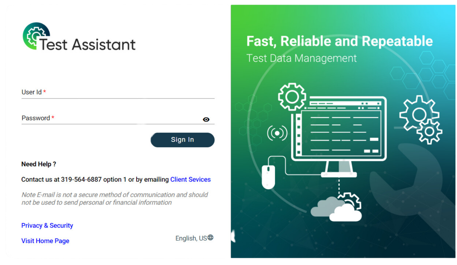
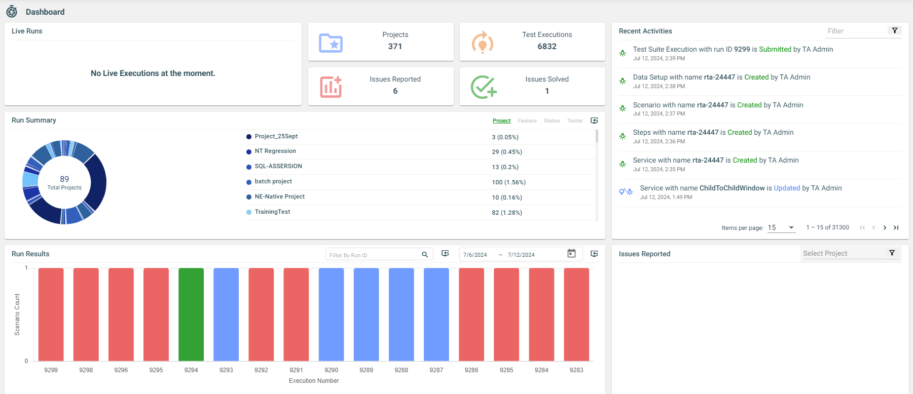
.png) icon, after which a drop down list will appear and you may choose your required filter. Multiple filters can be applied.
icon, after which a drop down list will appear and you may choose your required filter. Multiple filters can be applied. 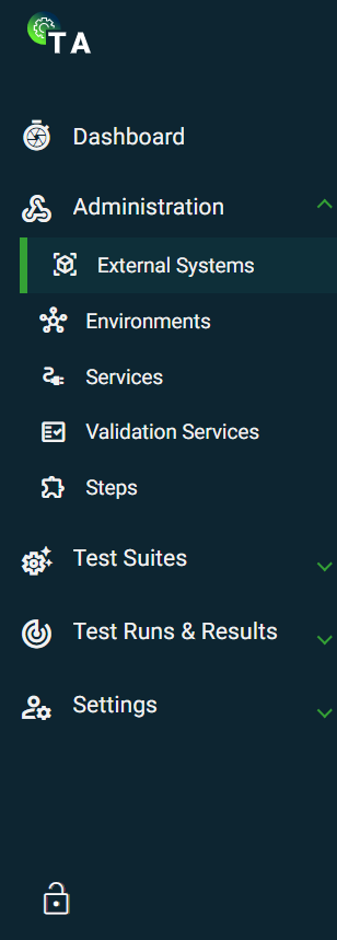
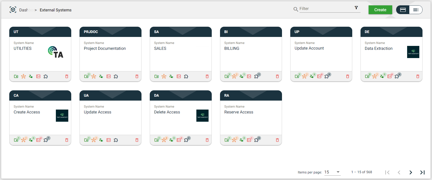
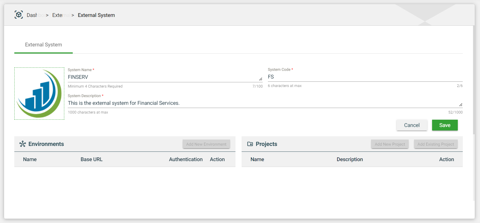
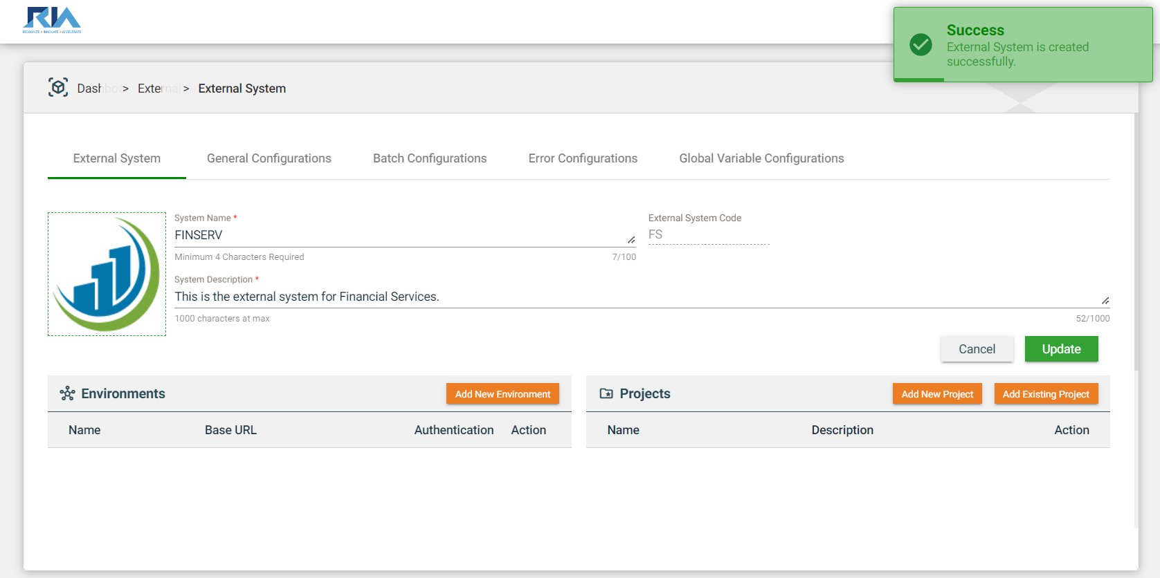
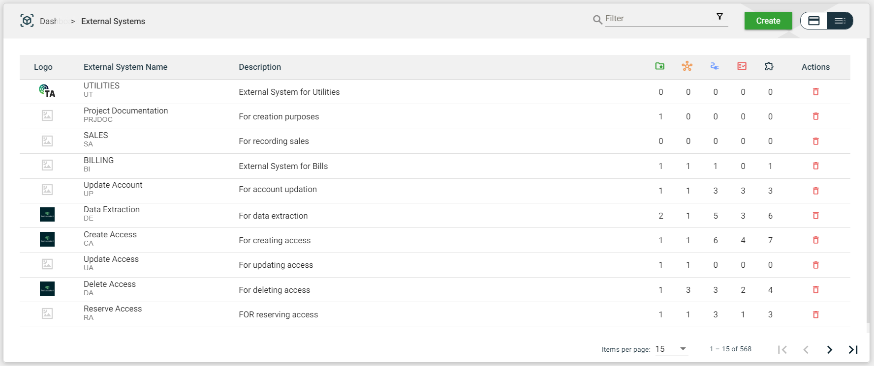
.png)
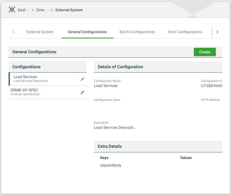
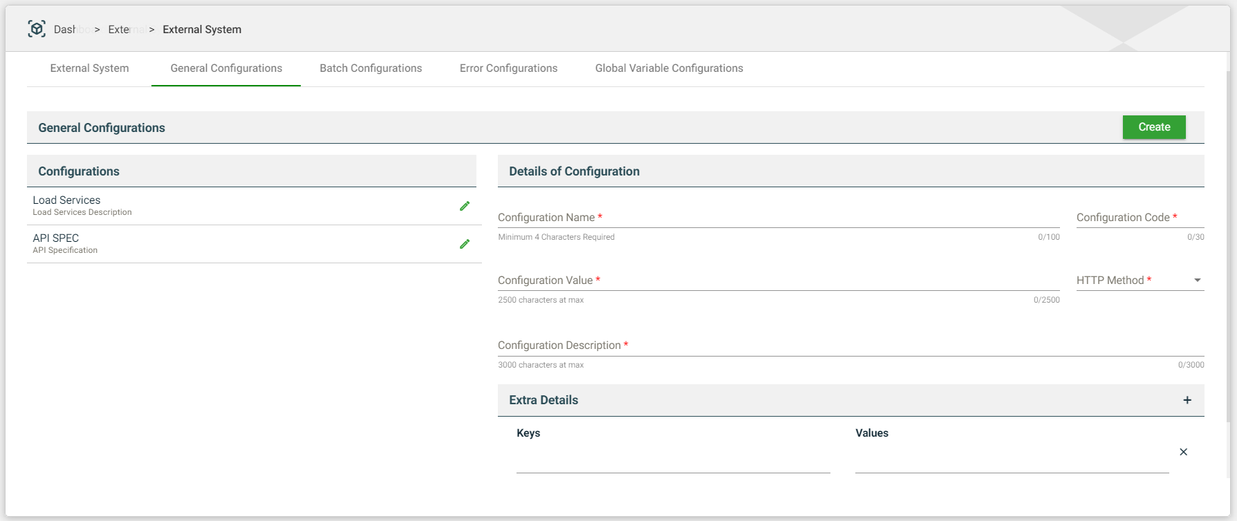
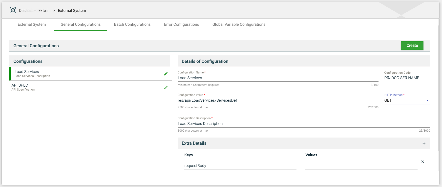
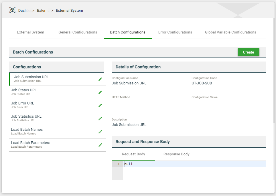
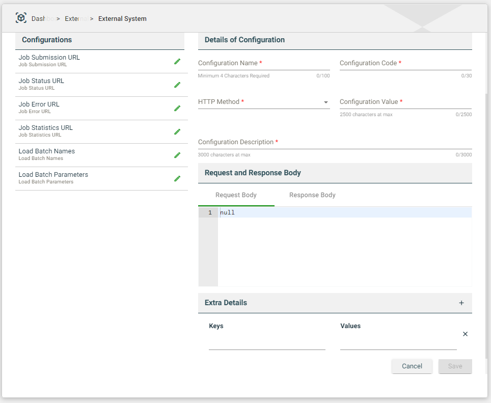
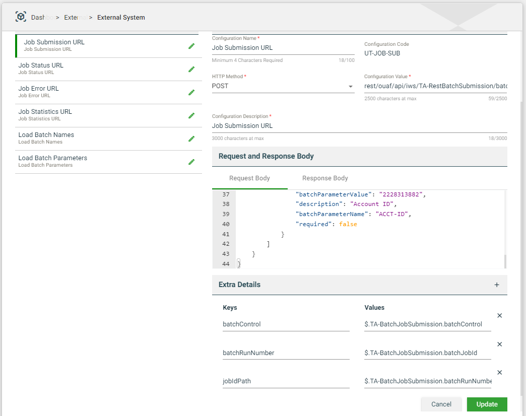
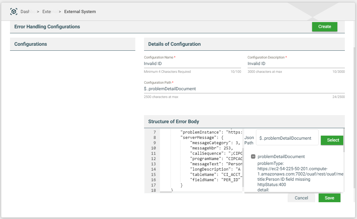
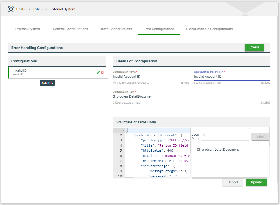
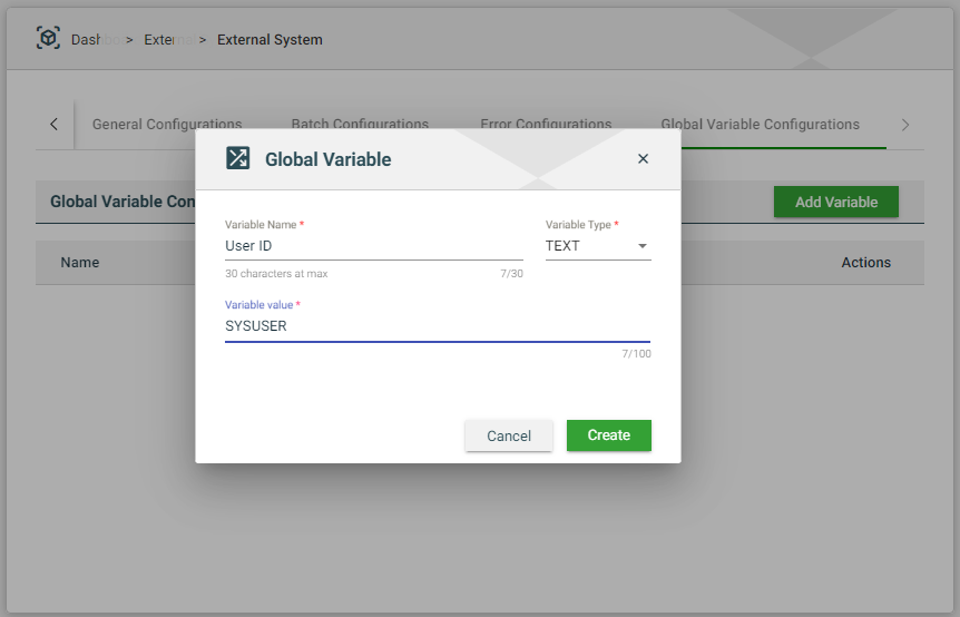
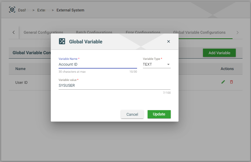
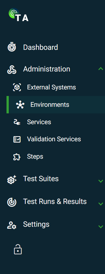

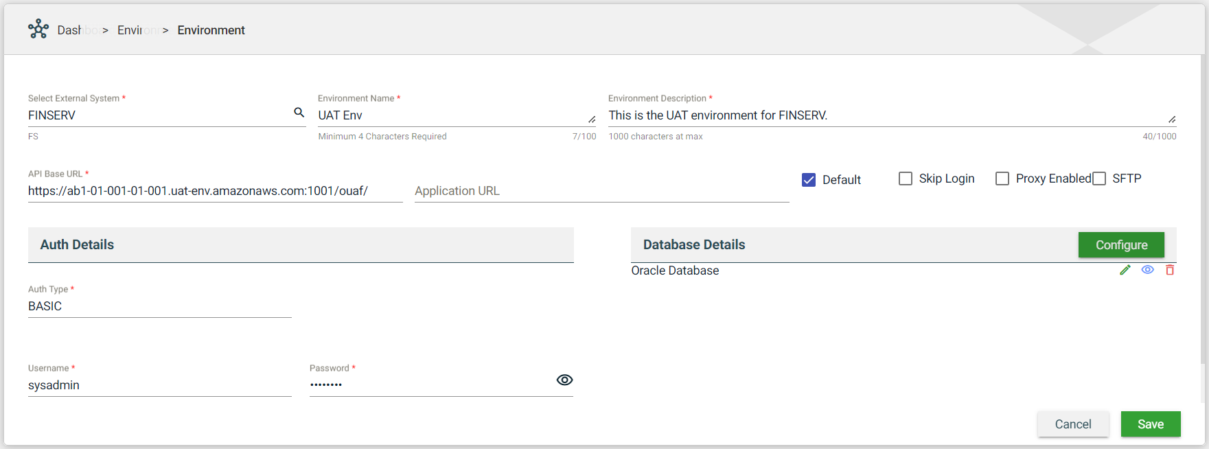
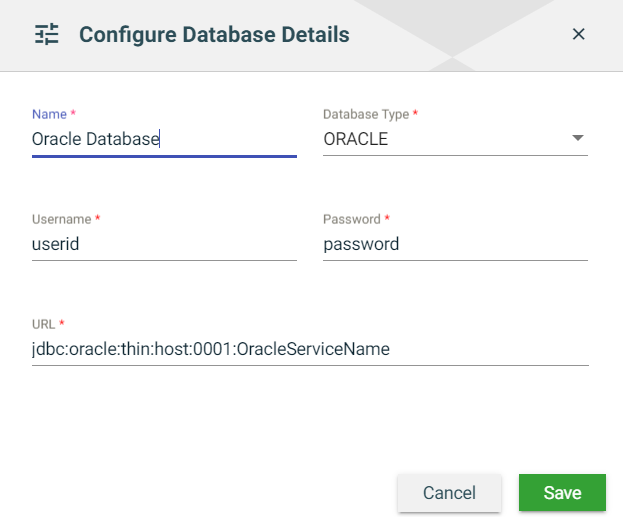
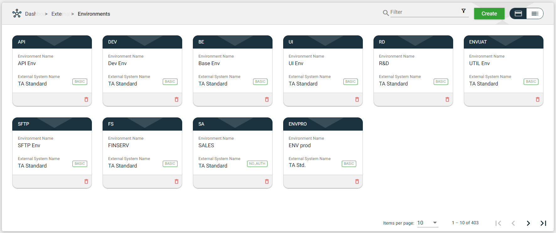
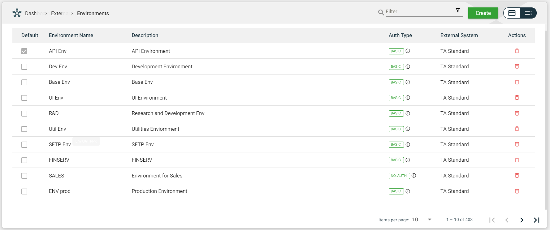
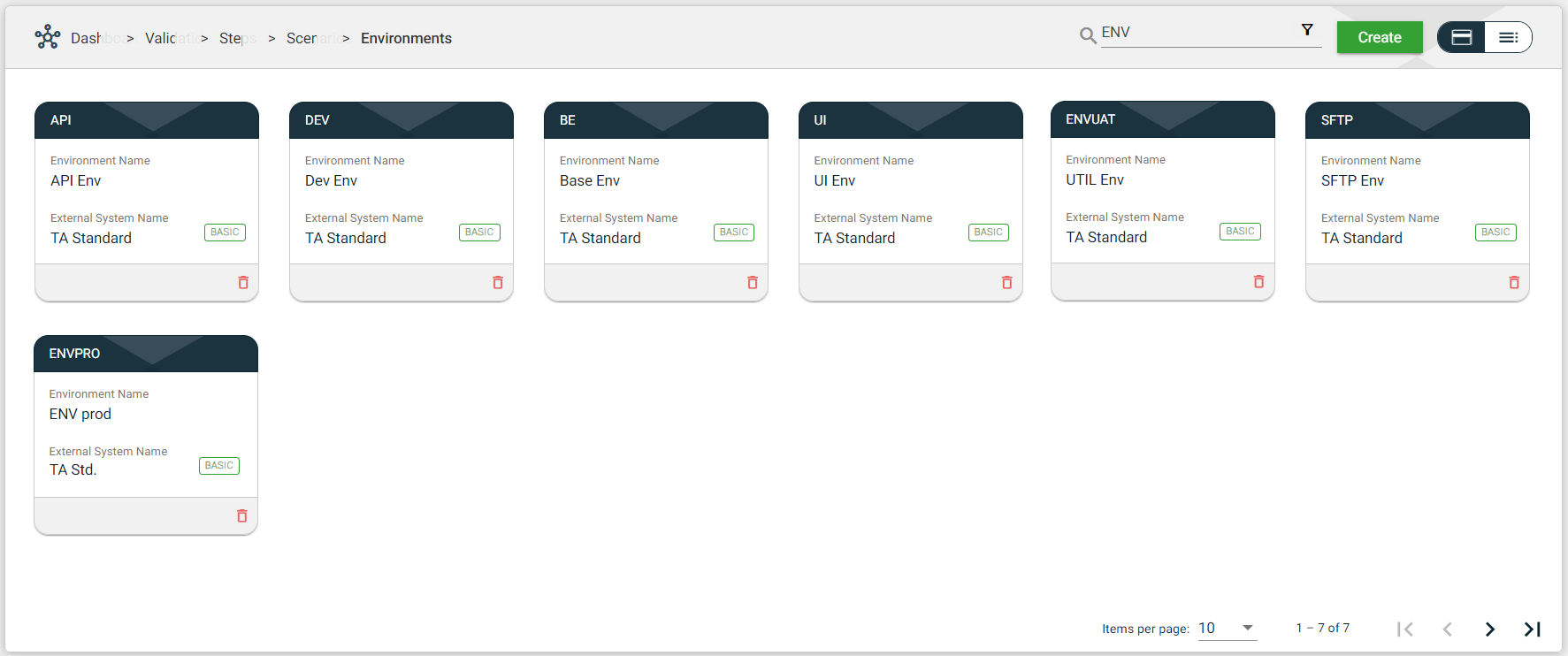
.png) to open the Filter Criteria for External System Name. Only the environment with a configured external system that matches the provided keyword or name will be displayed in the view.
to open the Filter Criteria for External System Name. Only the environment with a configured external system that matches the provided keyword or name will be displayed in the view. 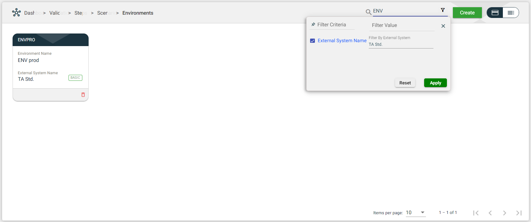
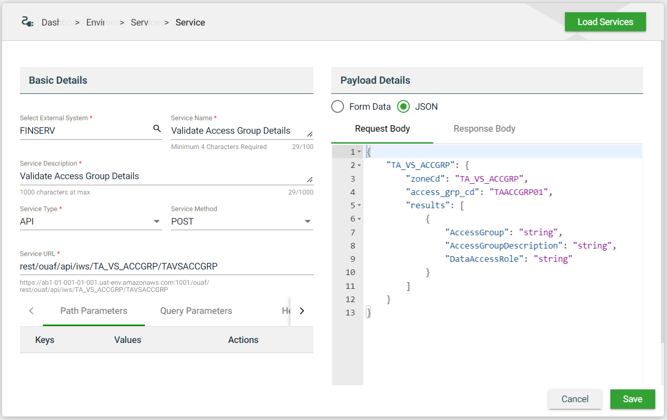
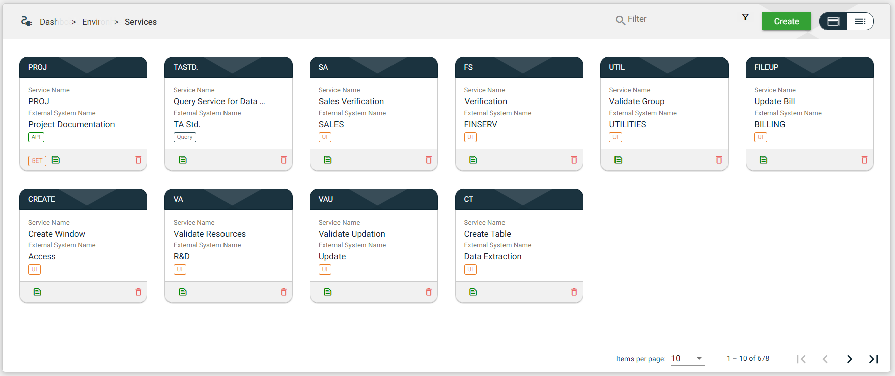
.png)
.png)
.png)
.png)
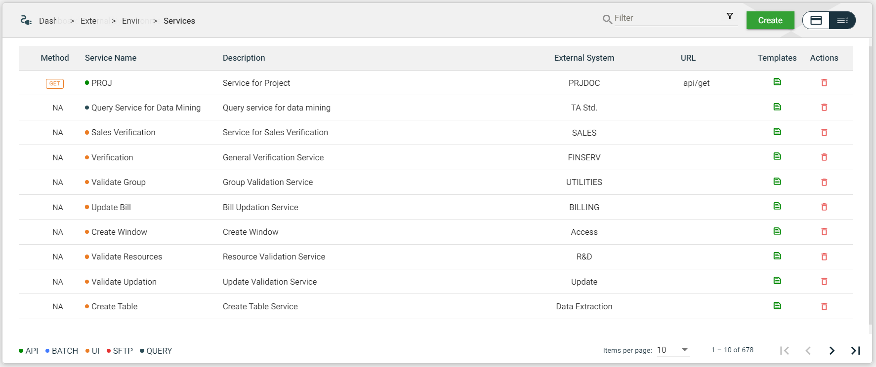
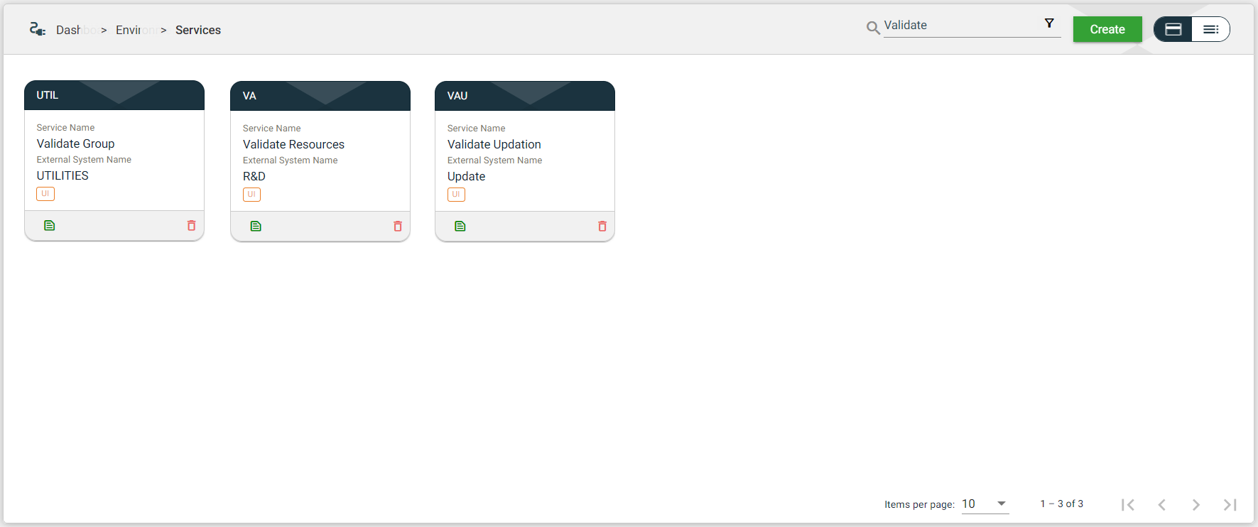
.png) to open the Filter Criteria for External System Name. Only the service with a configured external system that matches the provided keyword or name will be displayed in the view.
to open the Filter Criteria for External System Name. Only the service with a configured external system that matches the provided keyword or name will be displayed in the view. 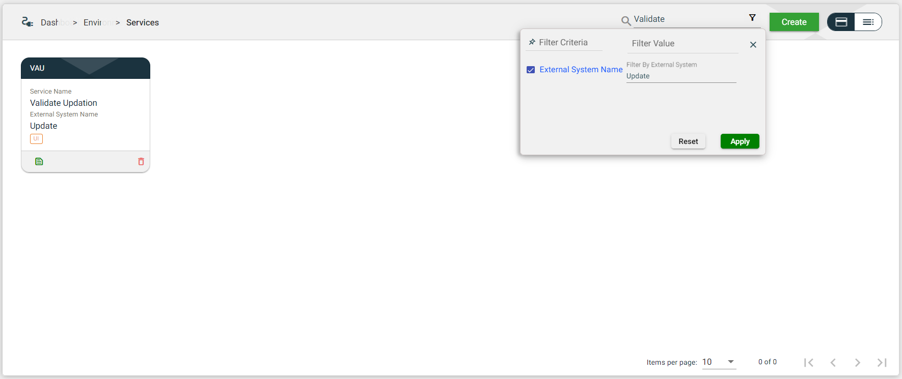
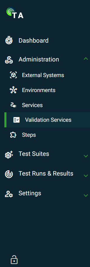
.png)
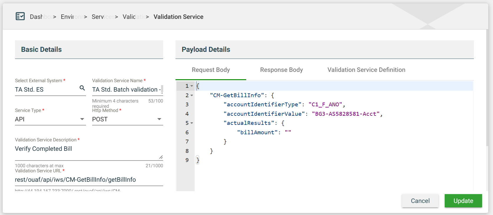
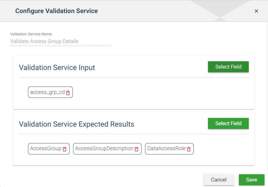
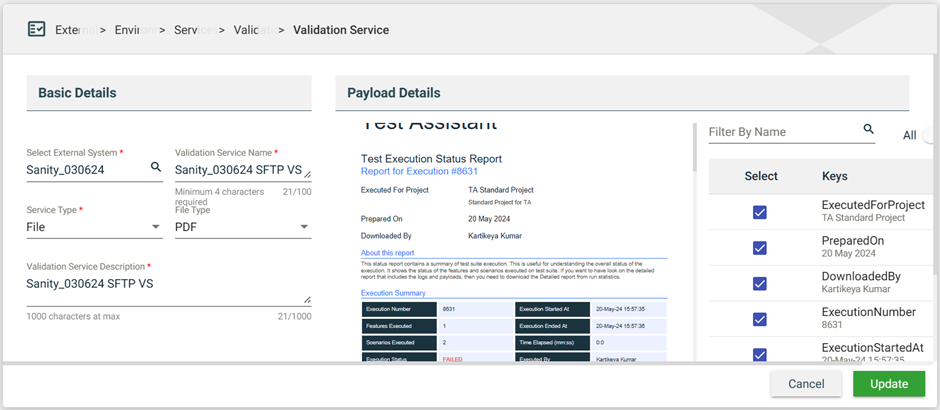
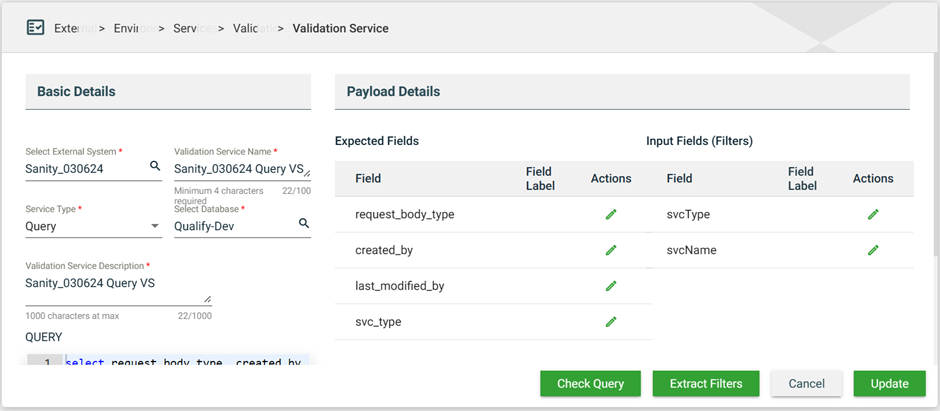
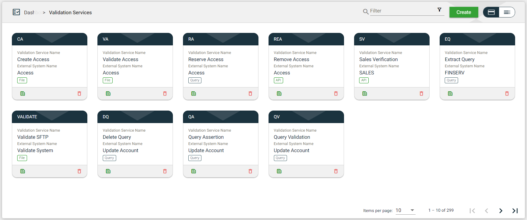
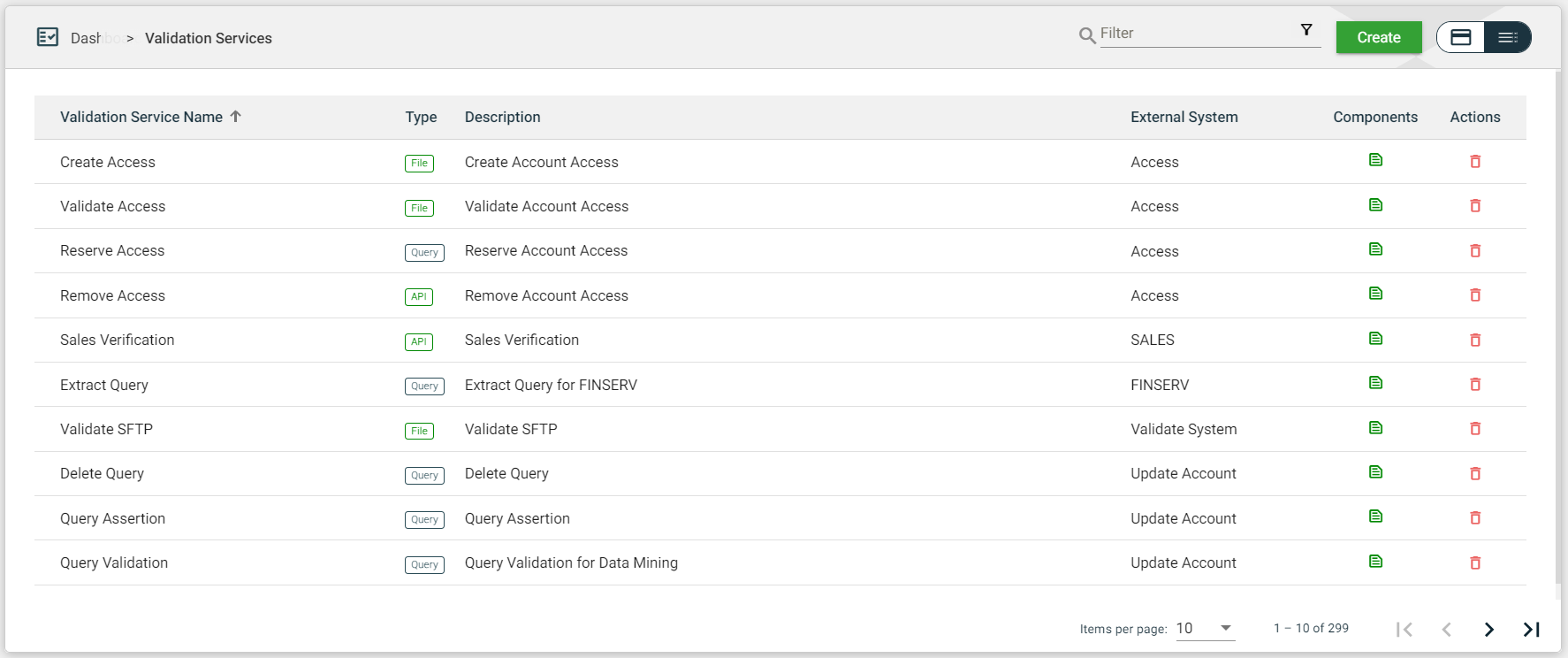
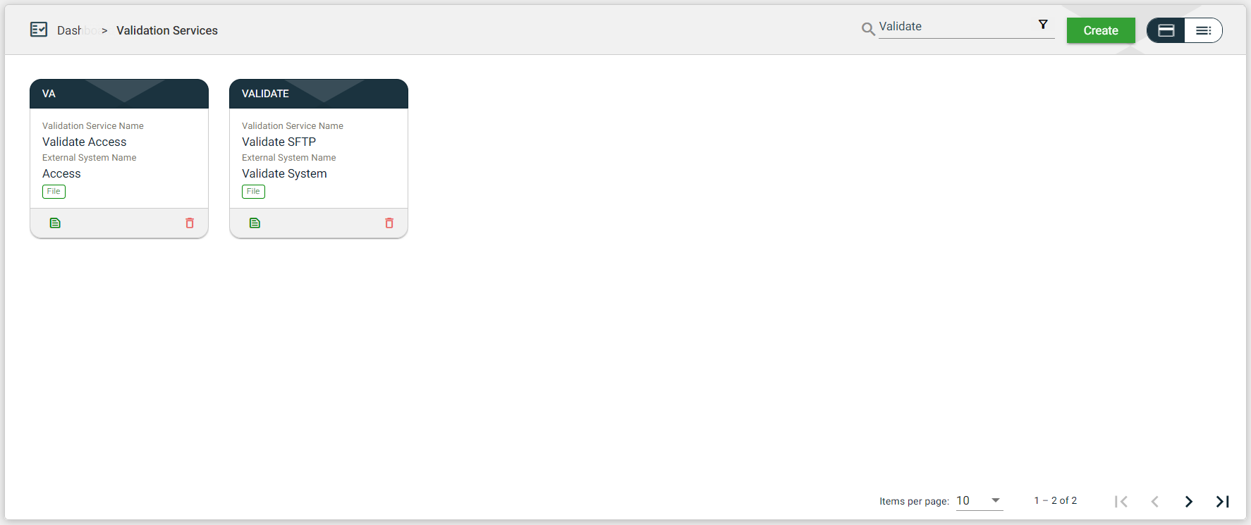

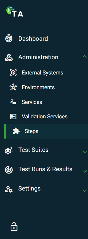
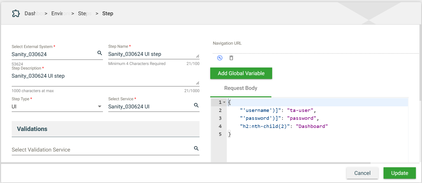
.png)
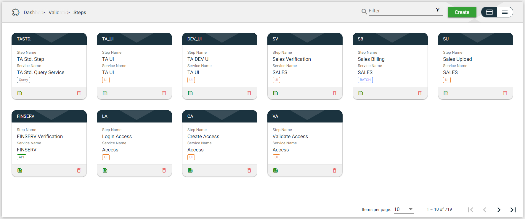
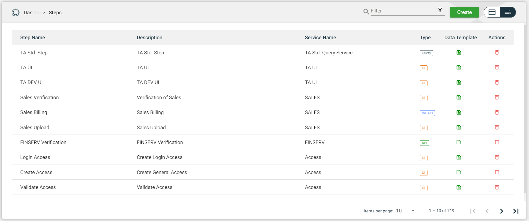
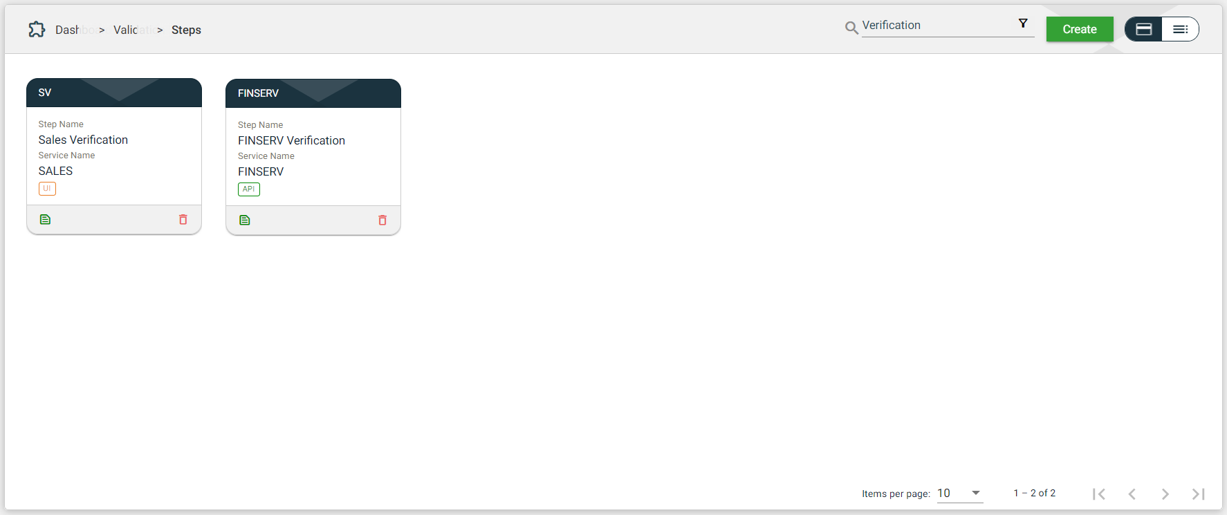

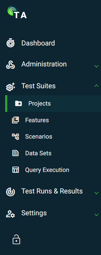
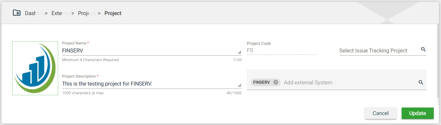
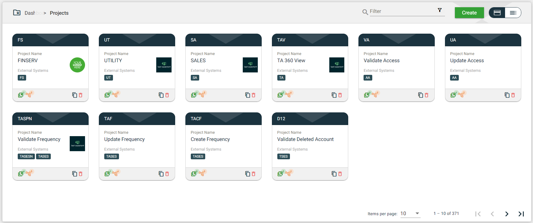
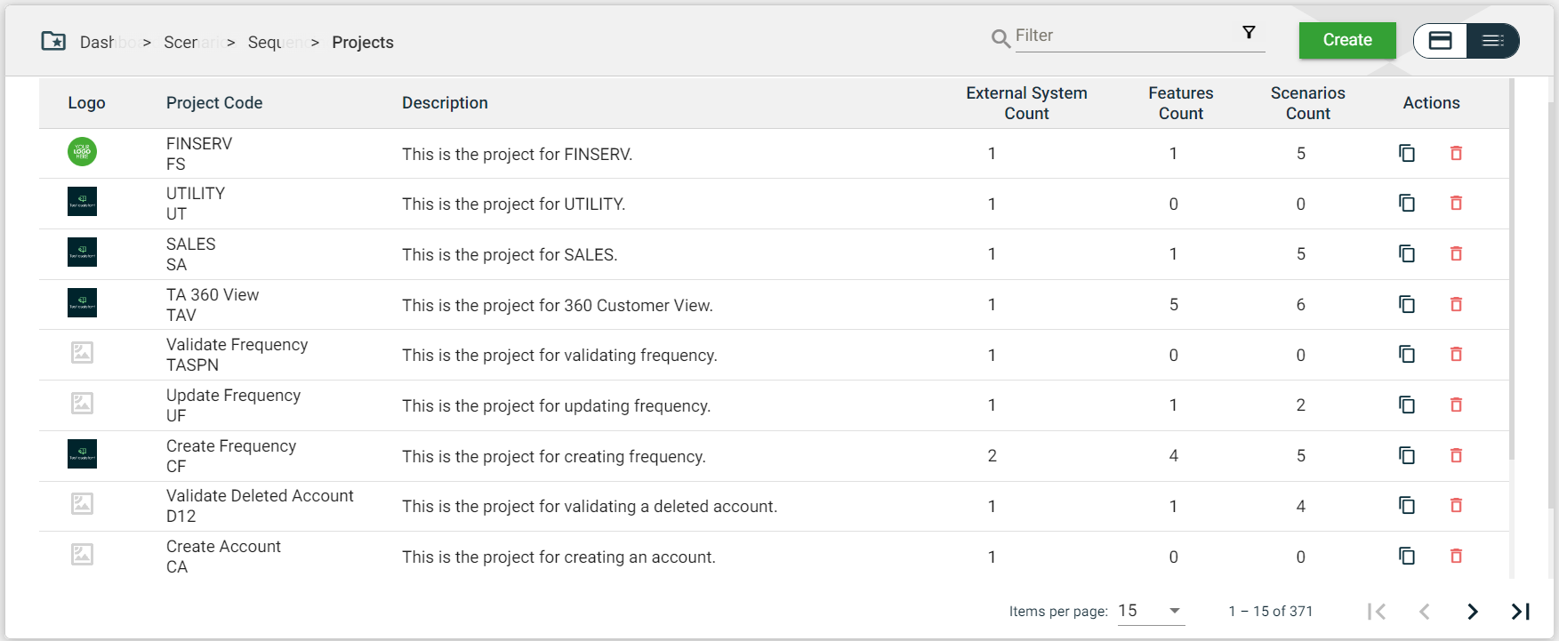
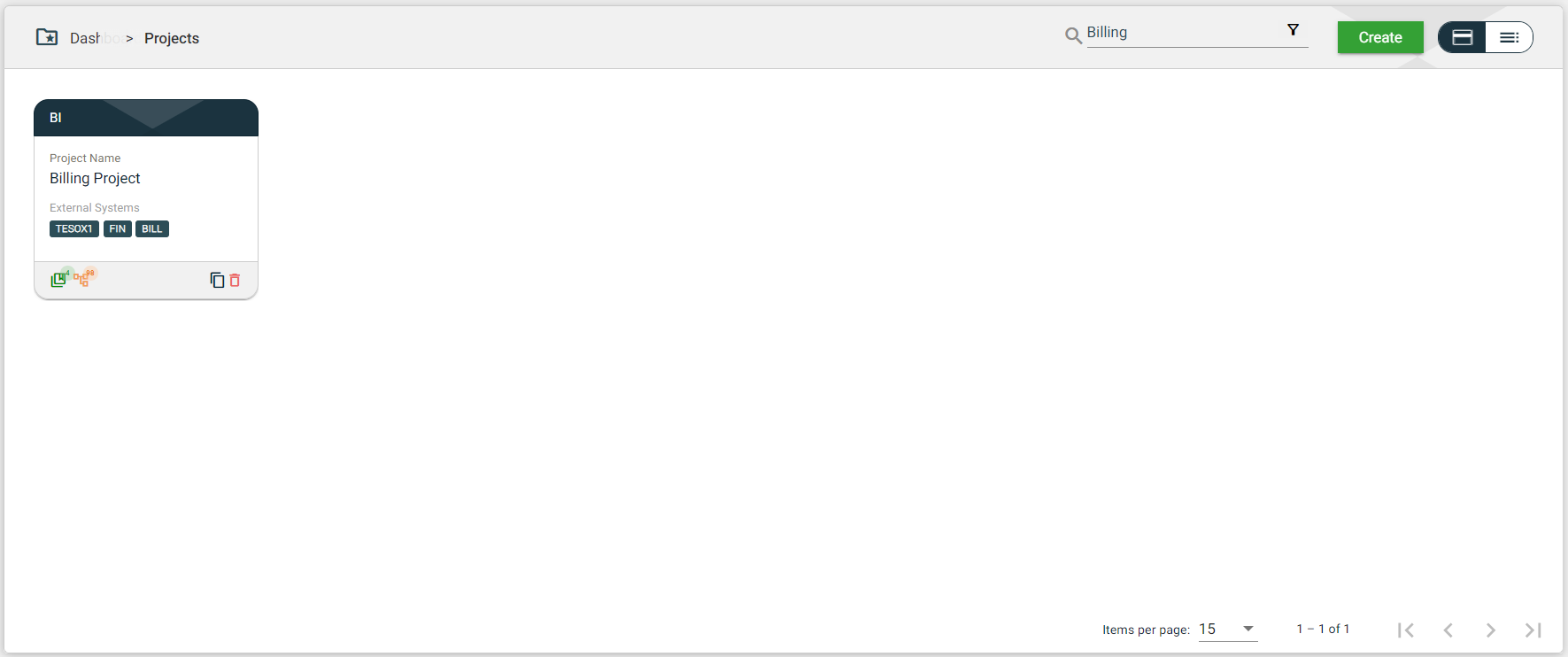
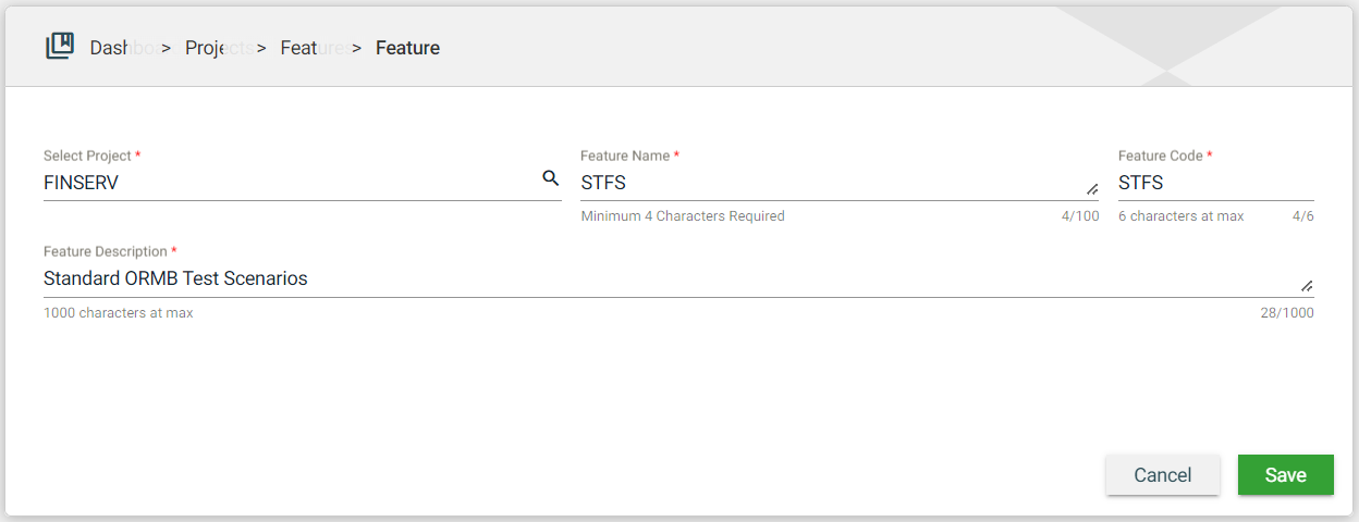
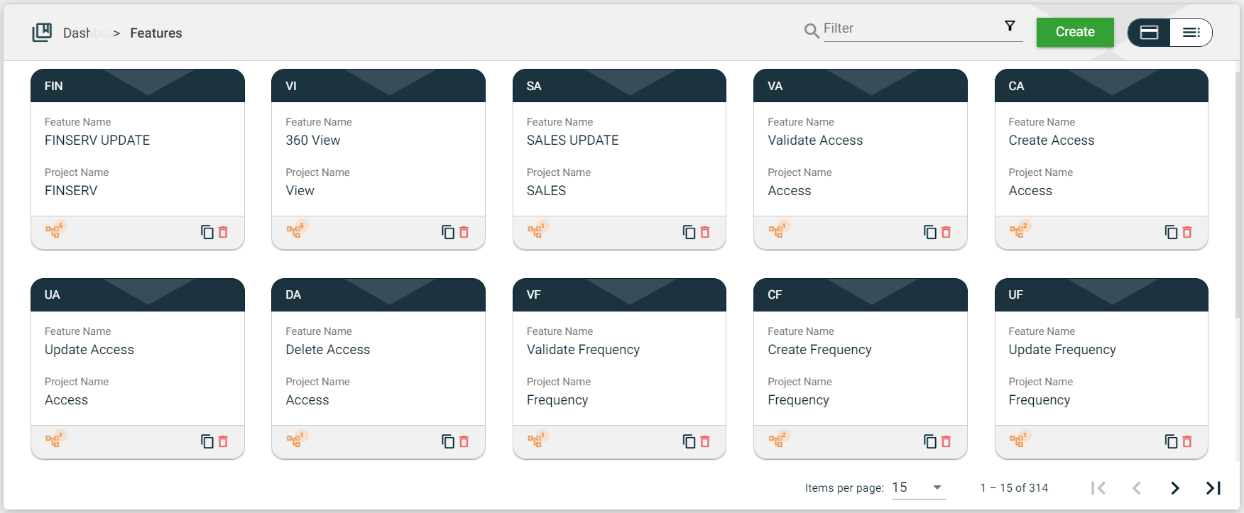
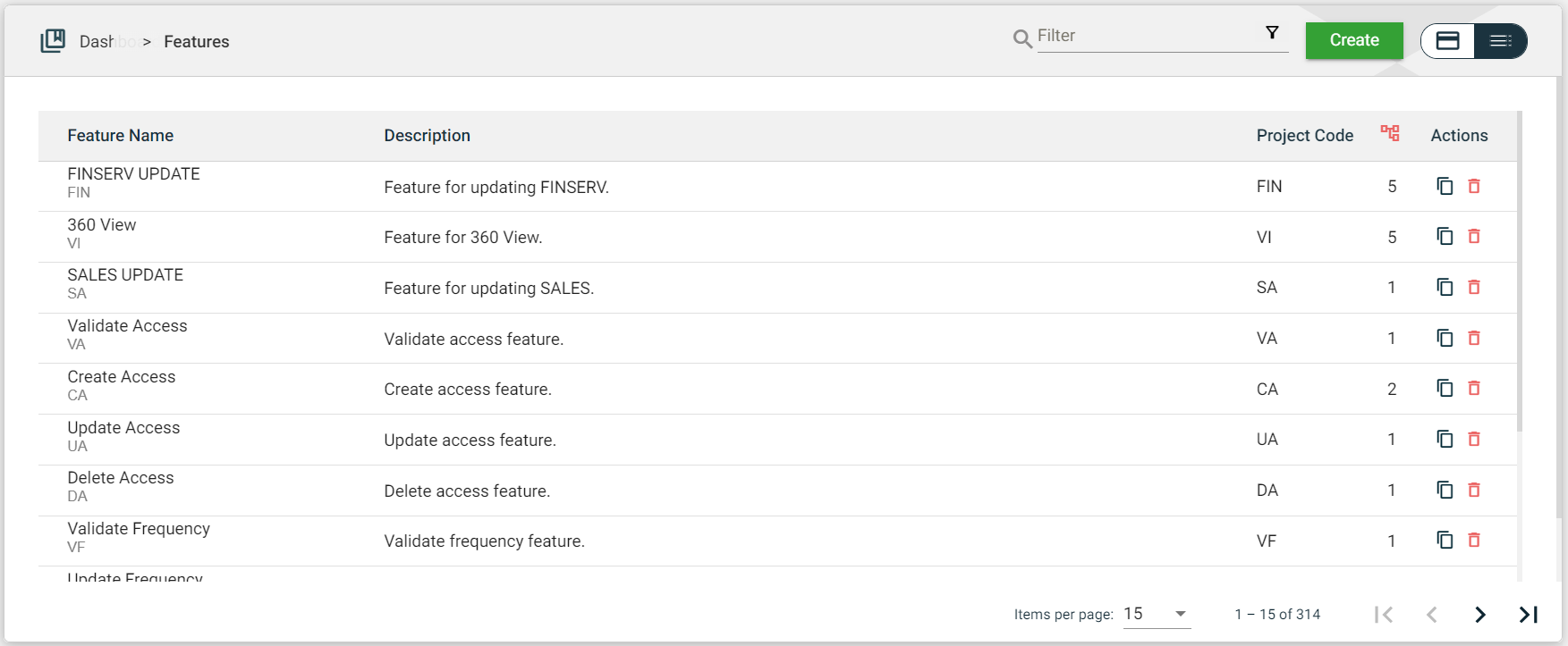
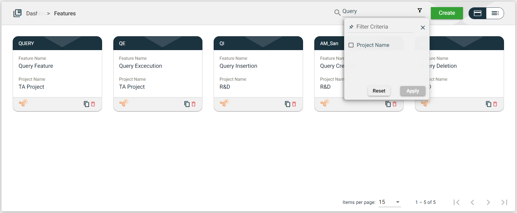
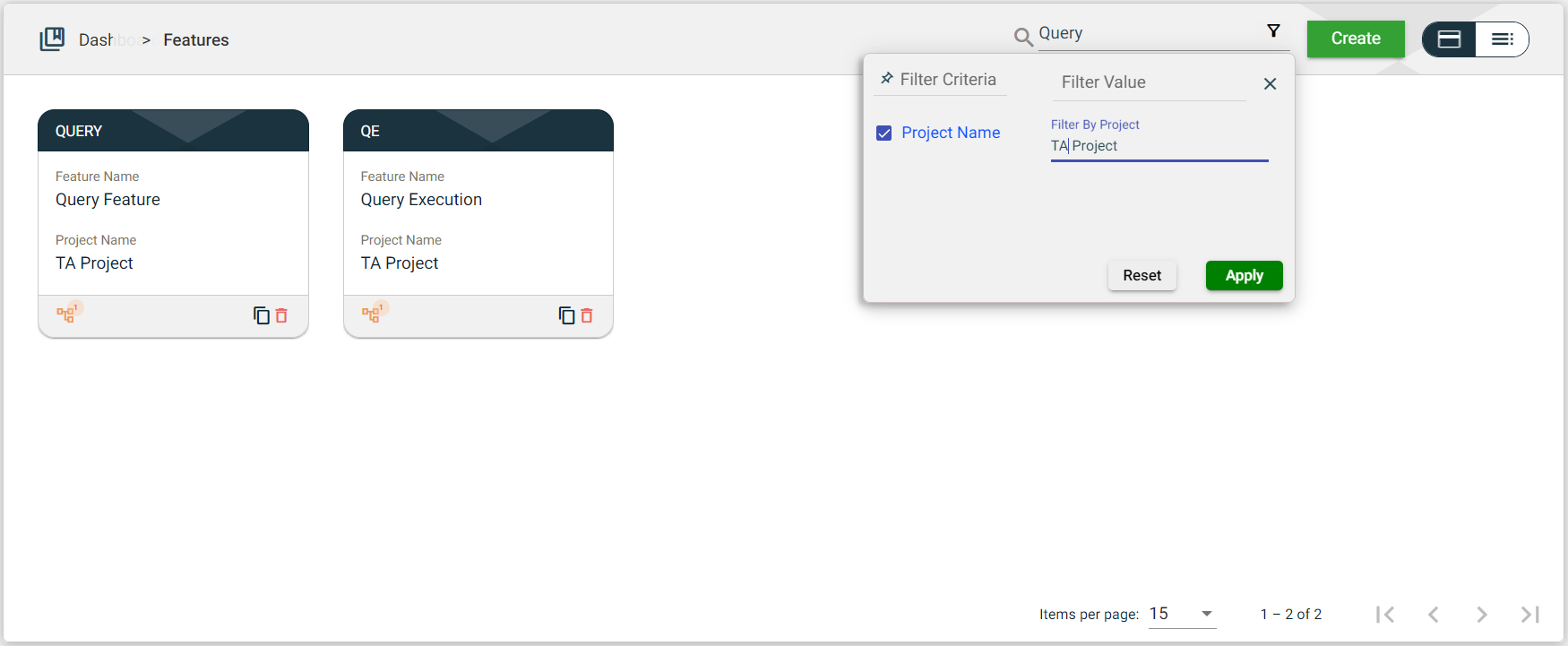
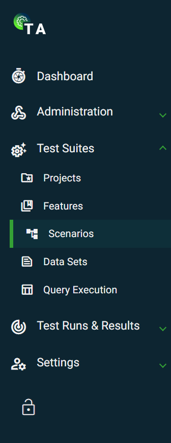
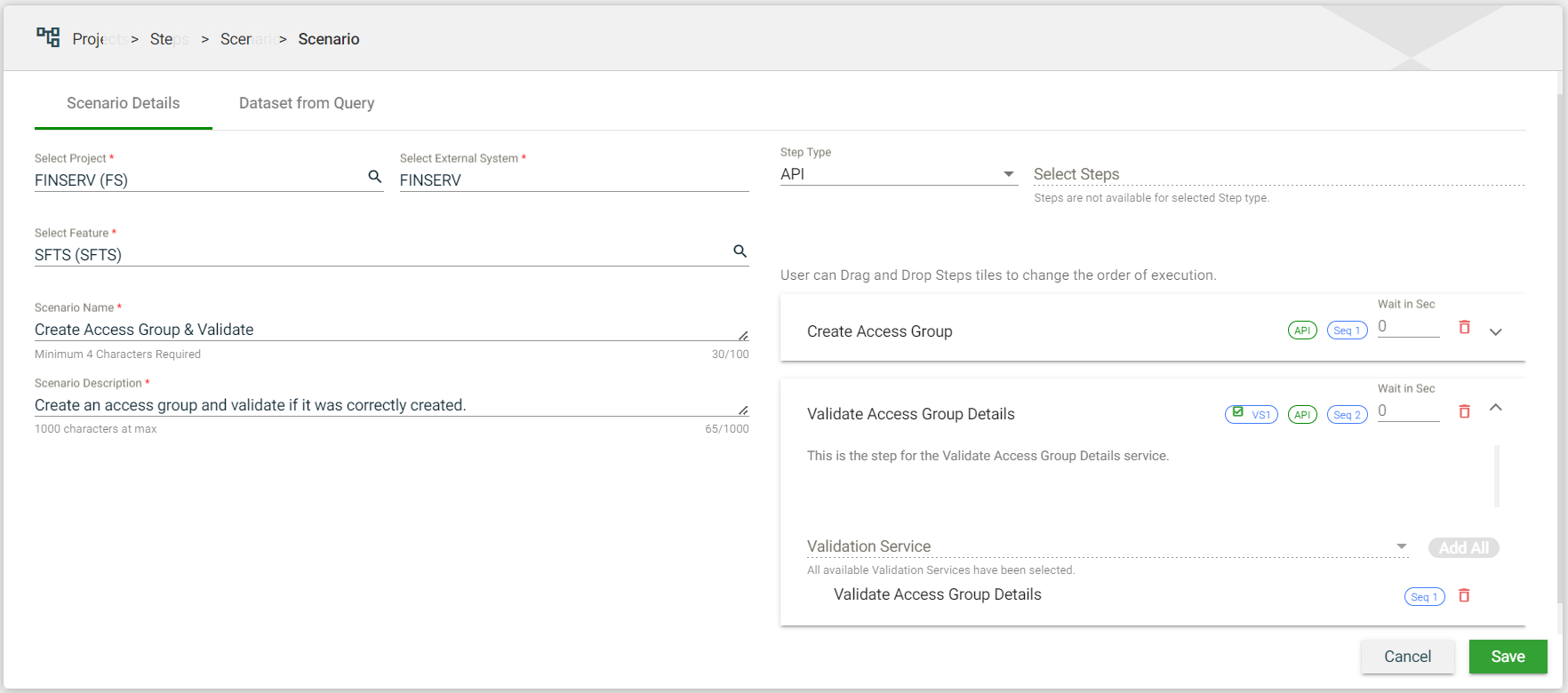
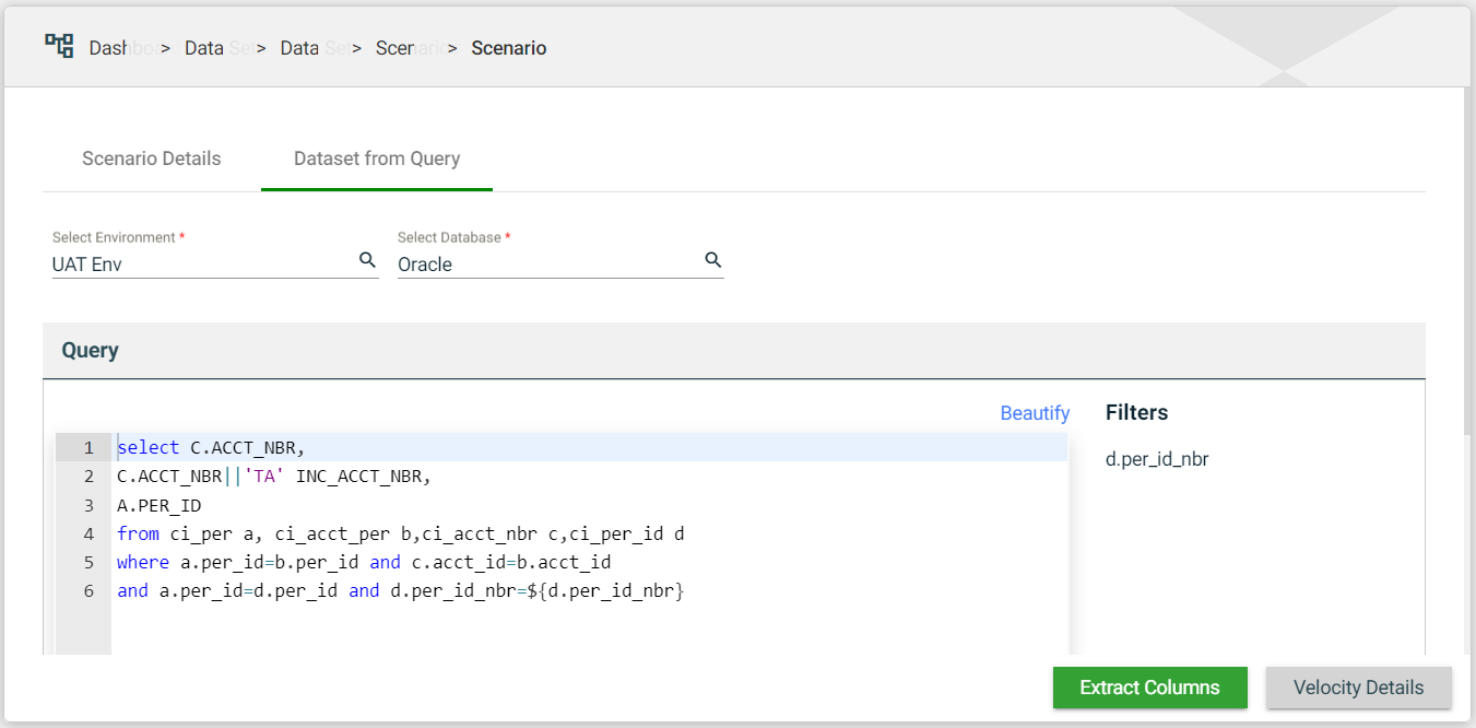
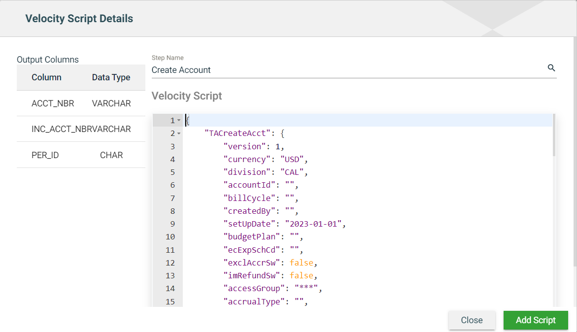
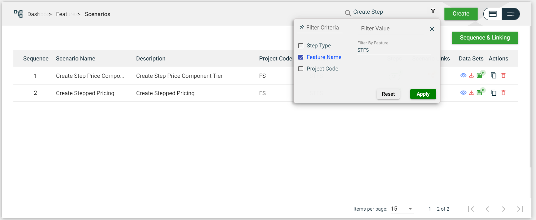
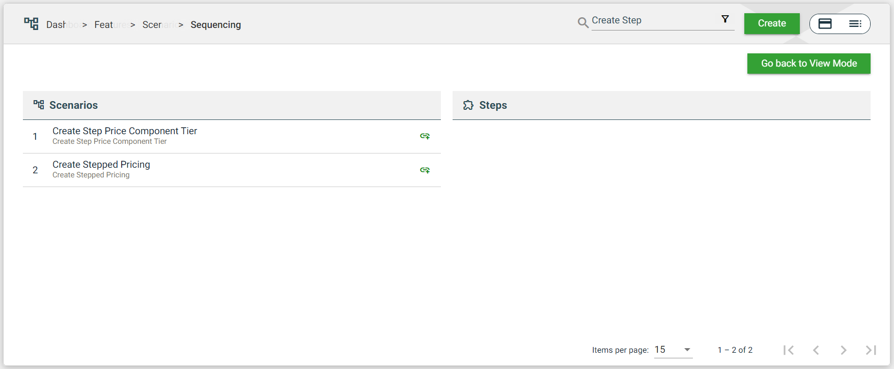
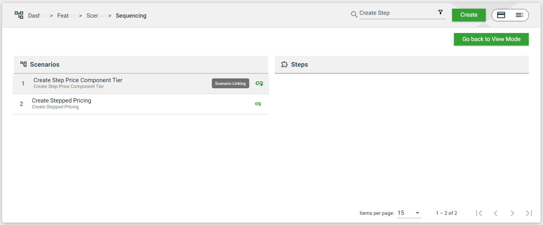
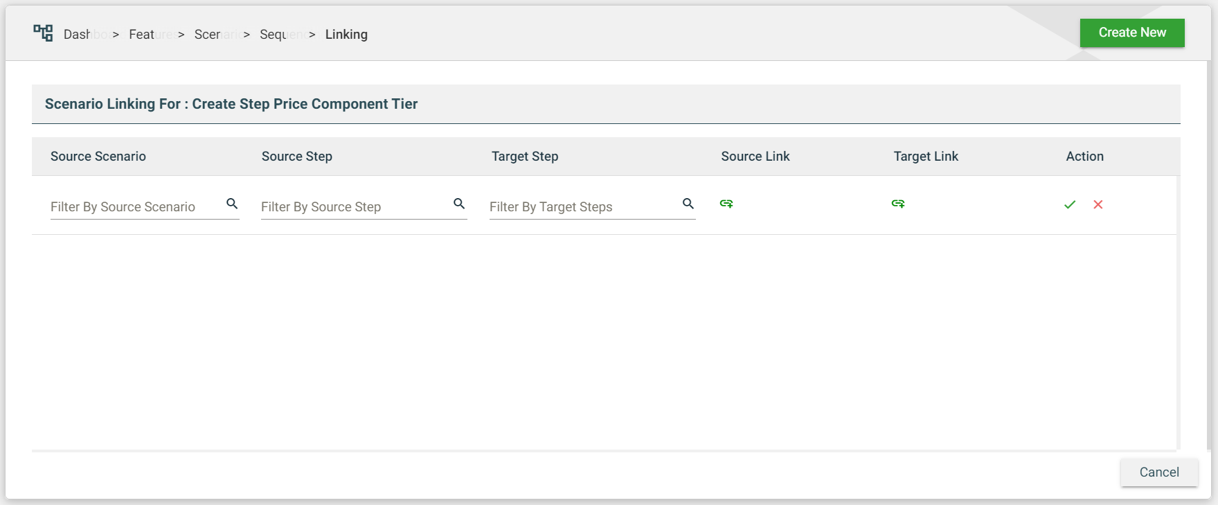
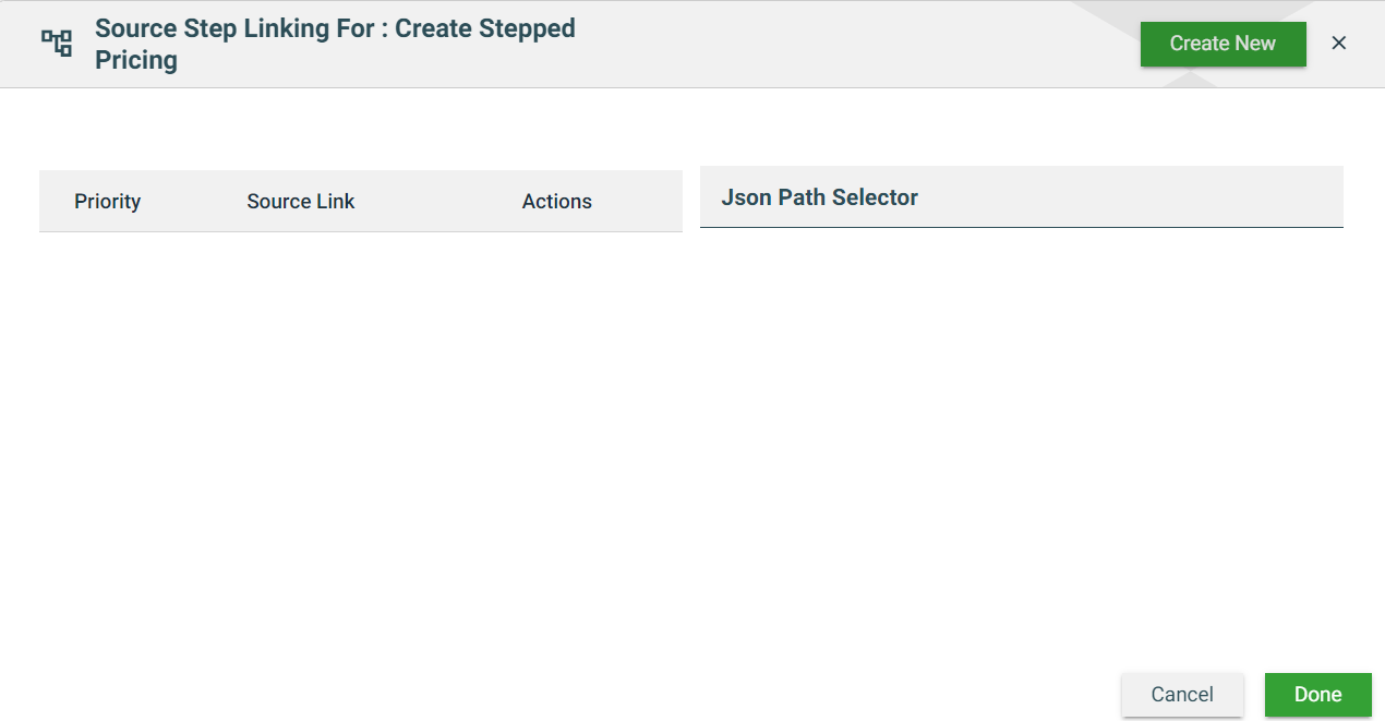
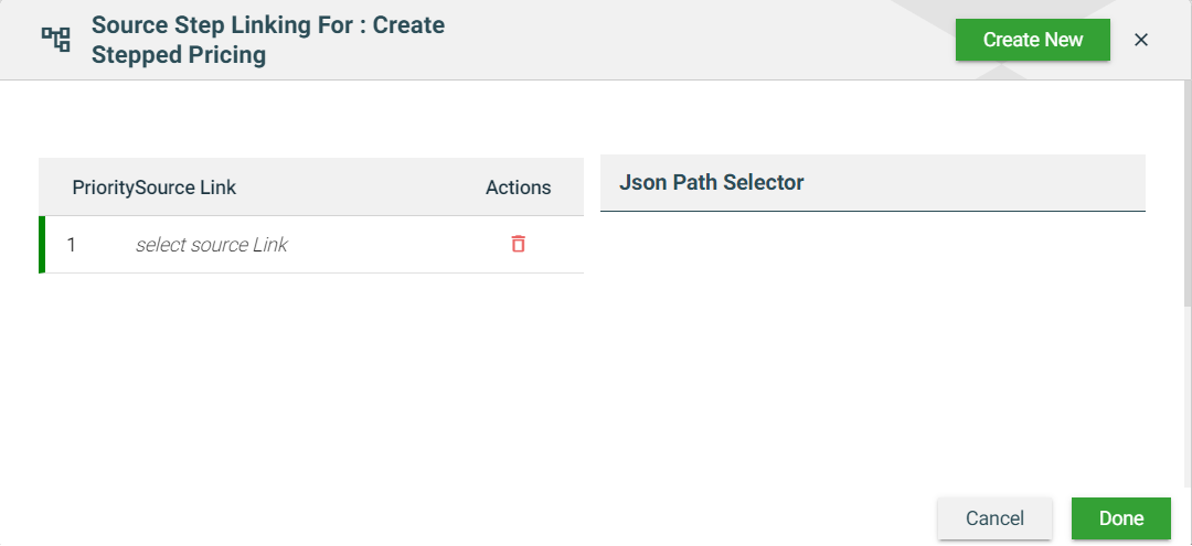
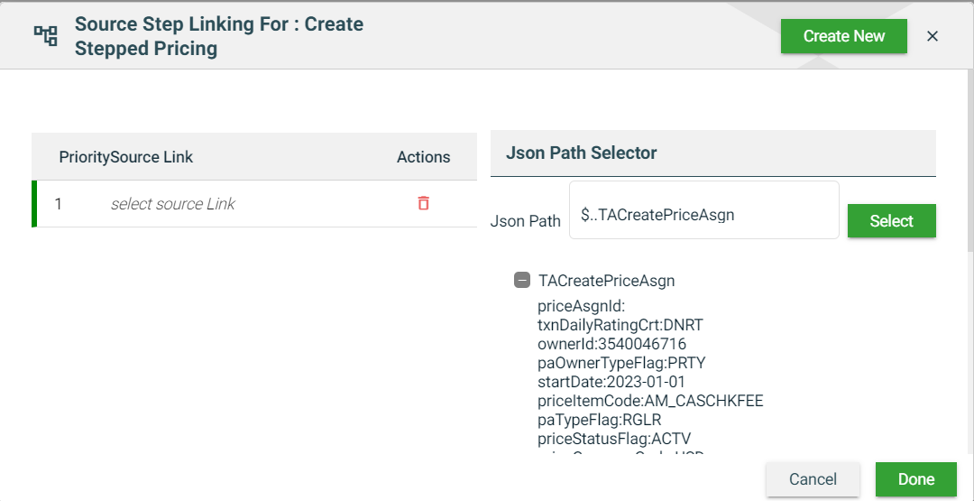
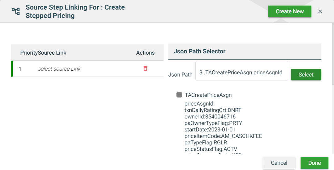
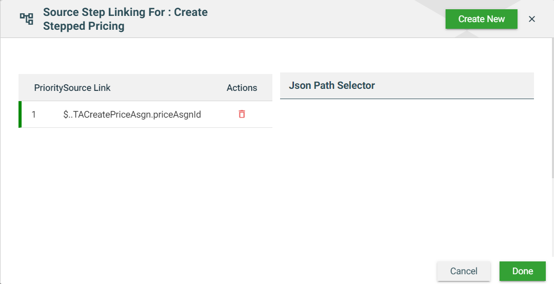
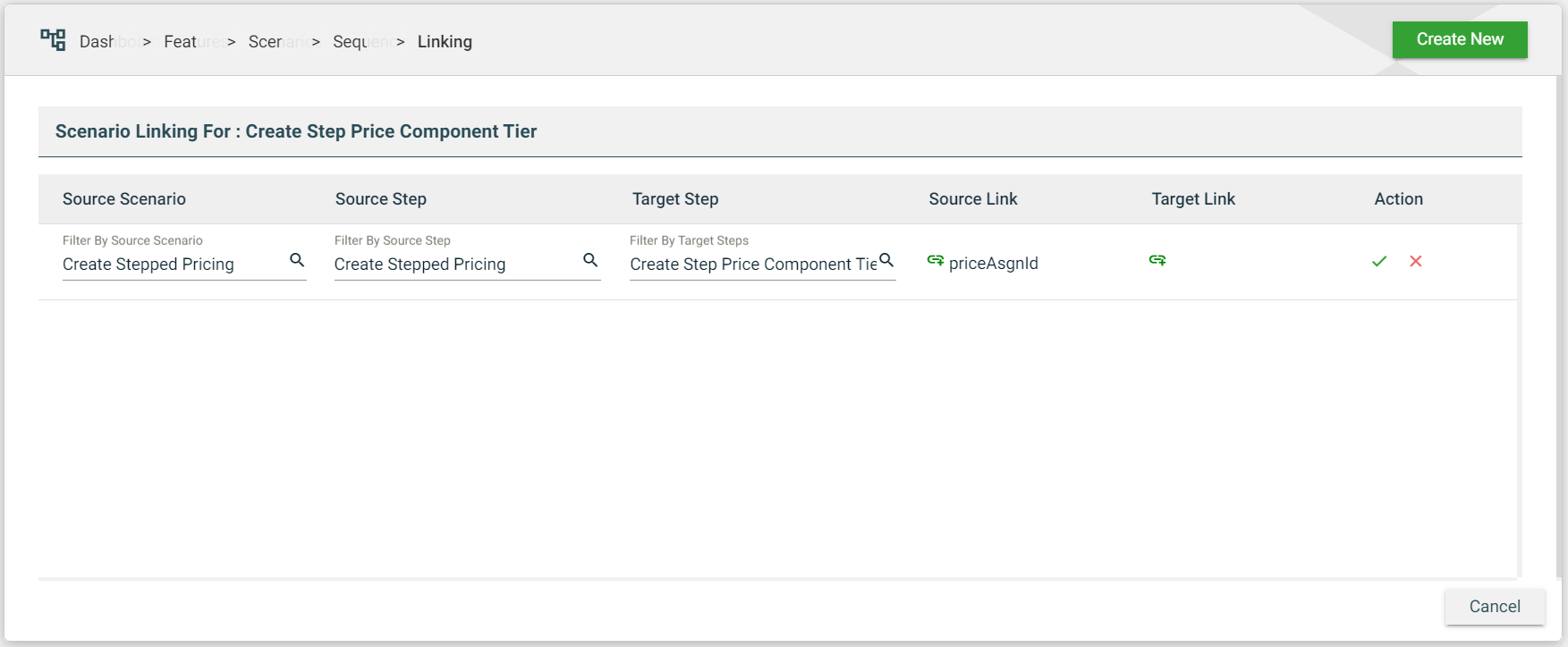
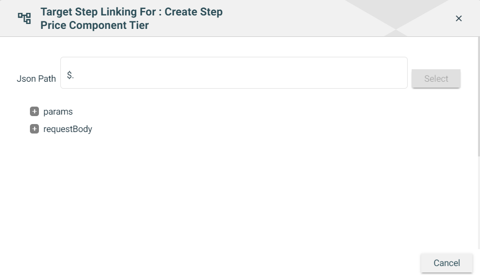
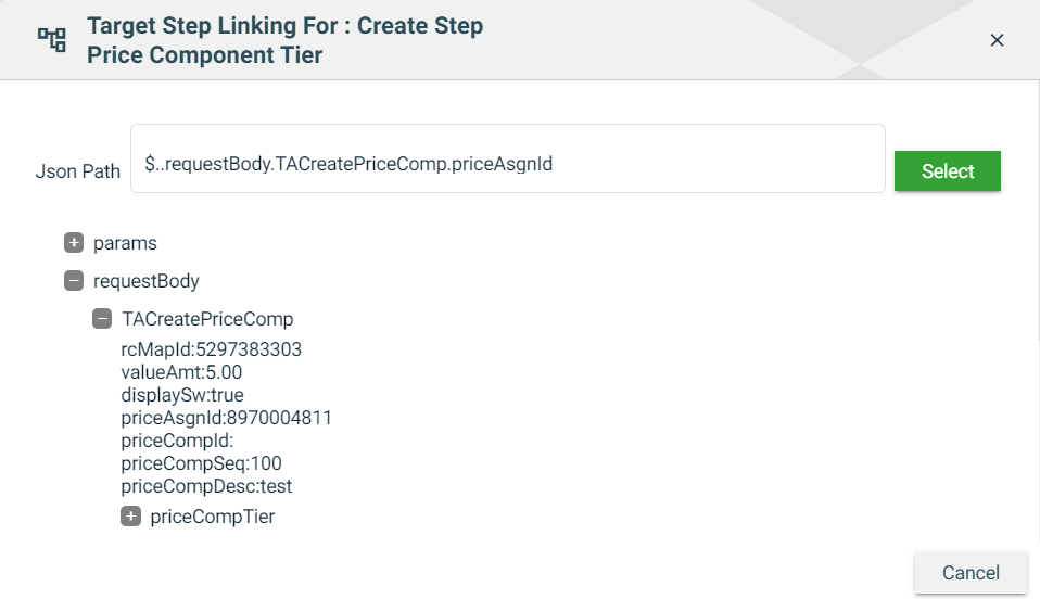
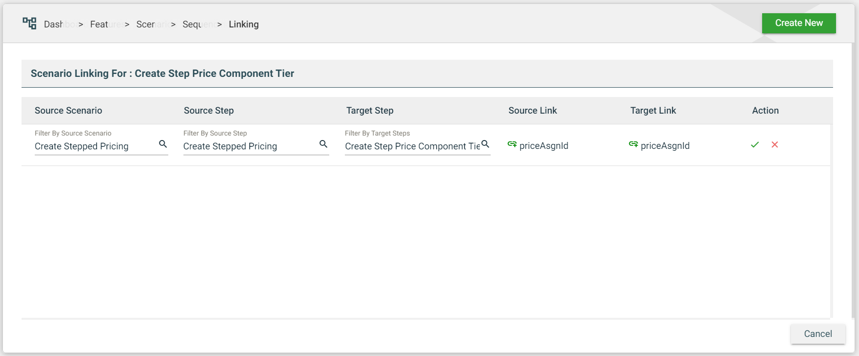
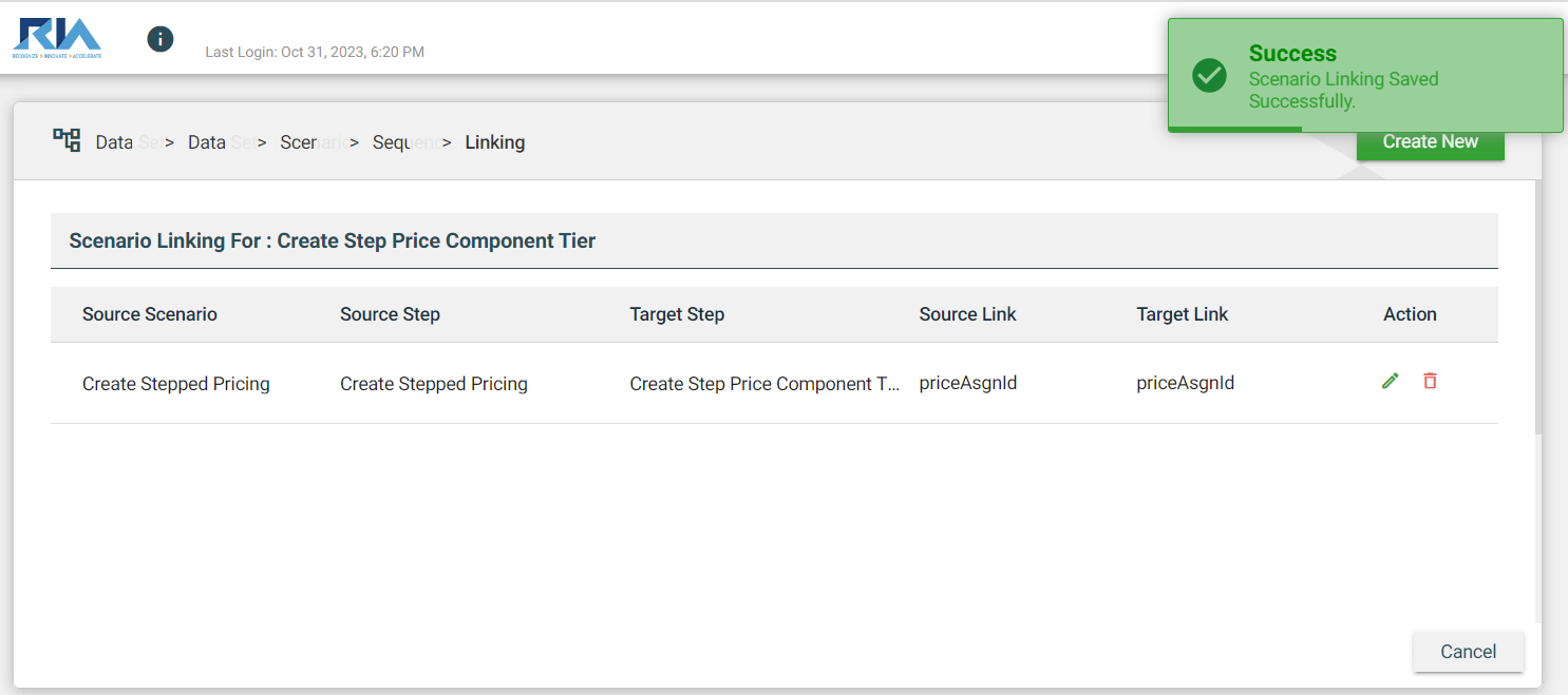
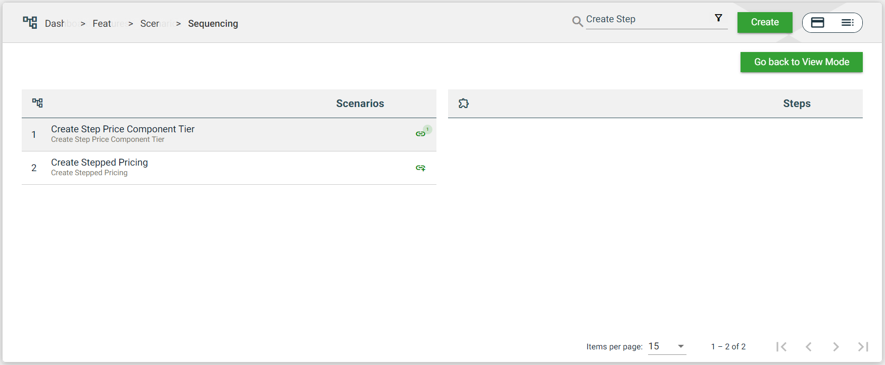
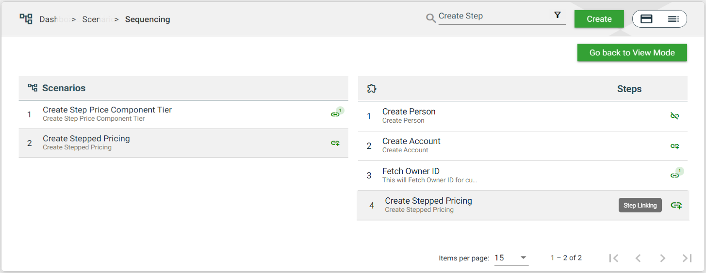

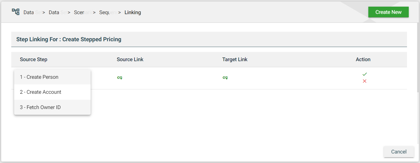
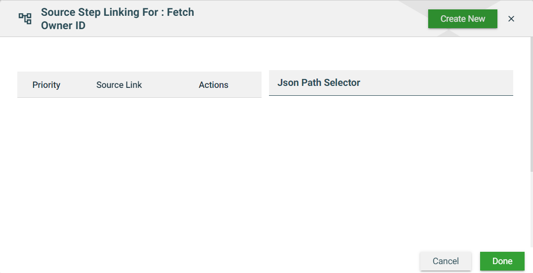
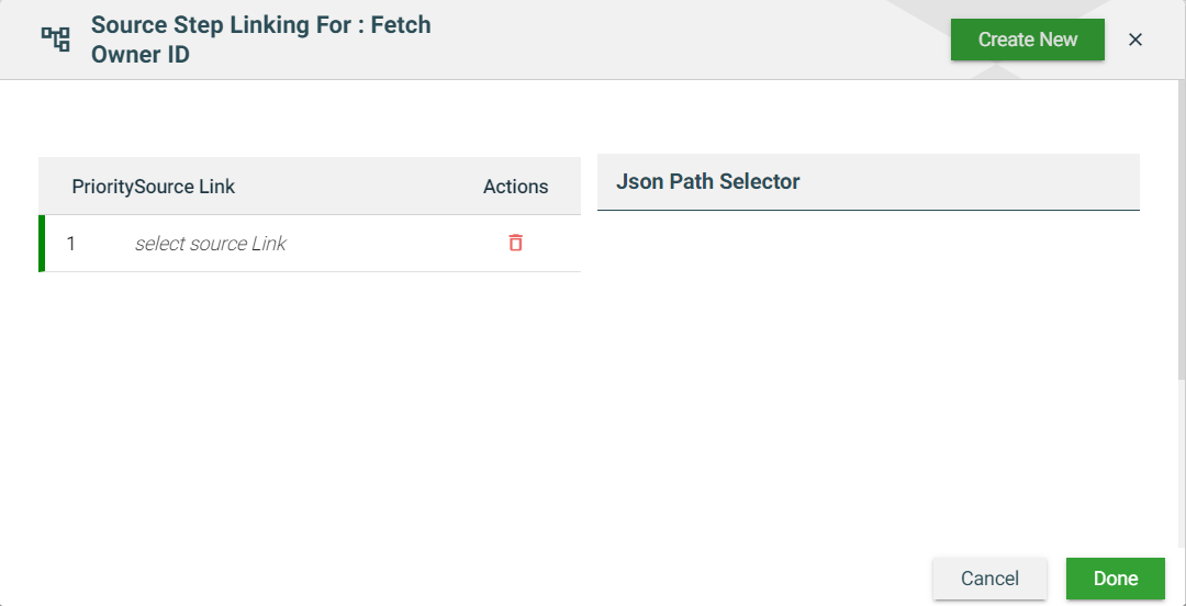
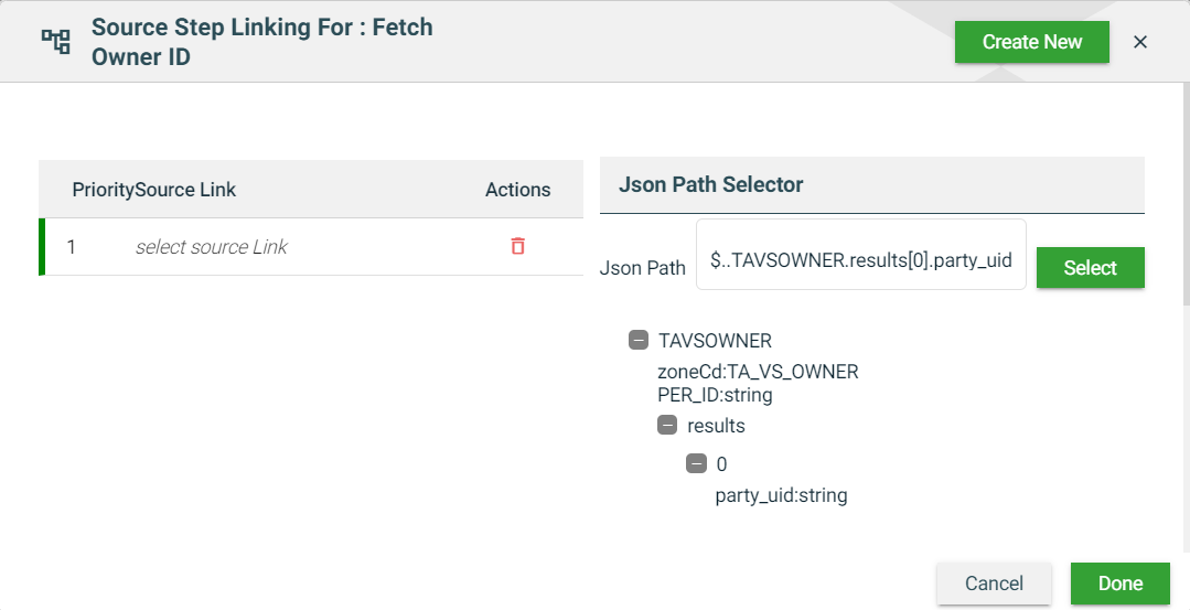
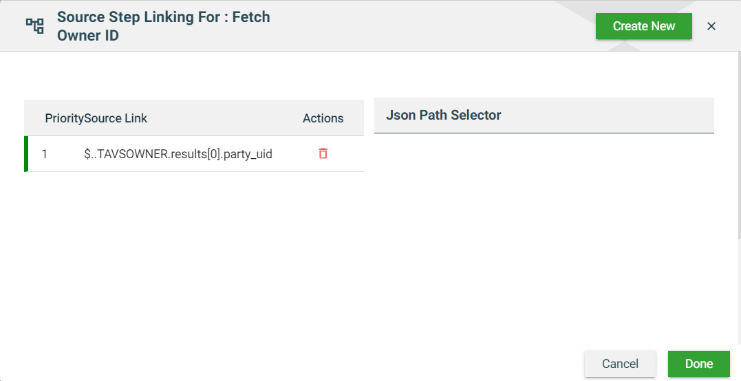
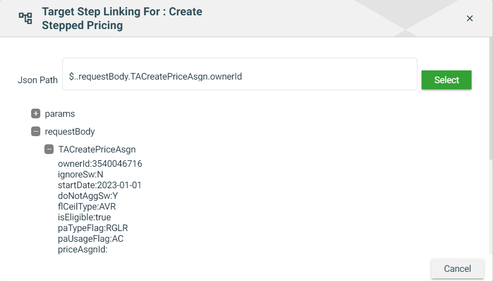
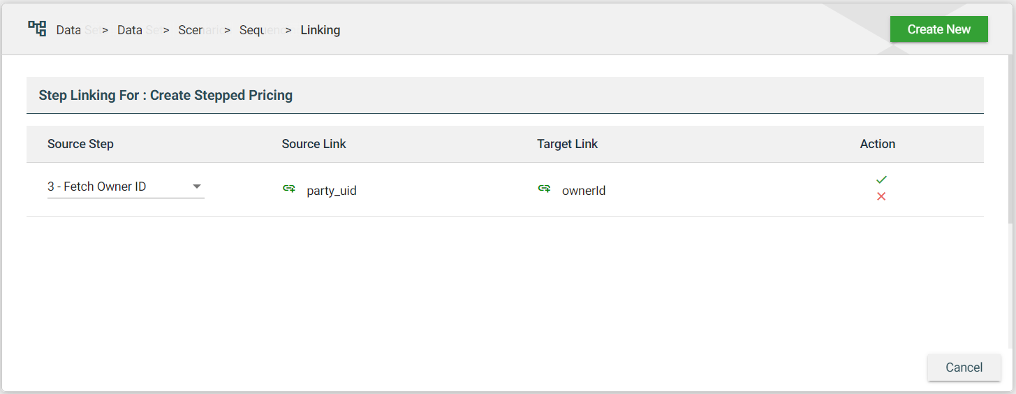
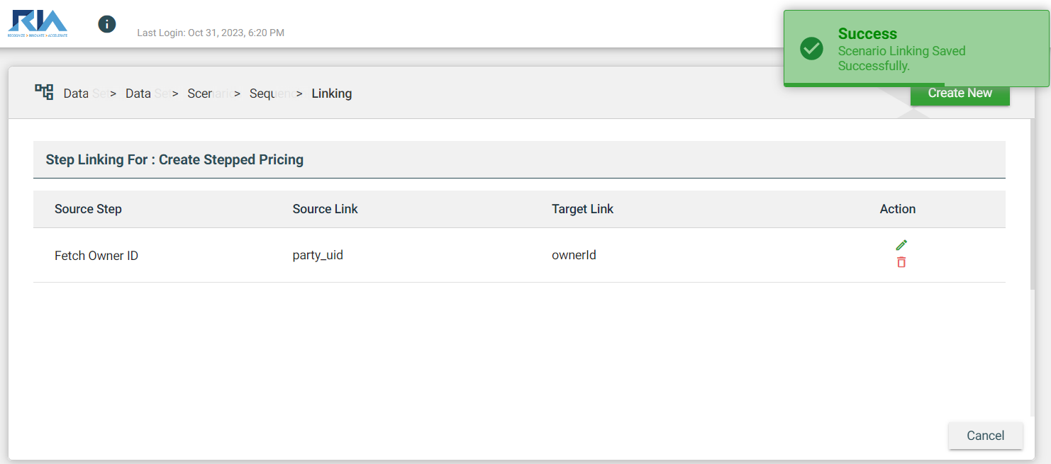
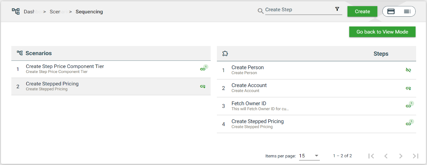
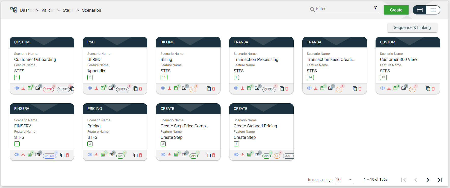
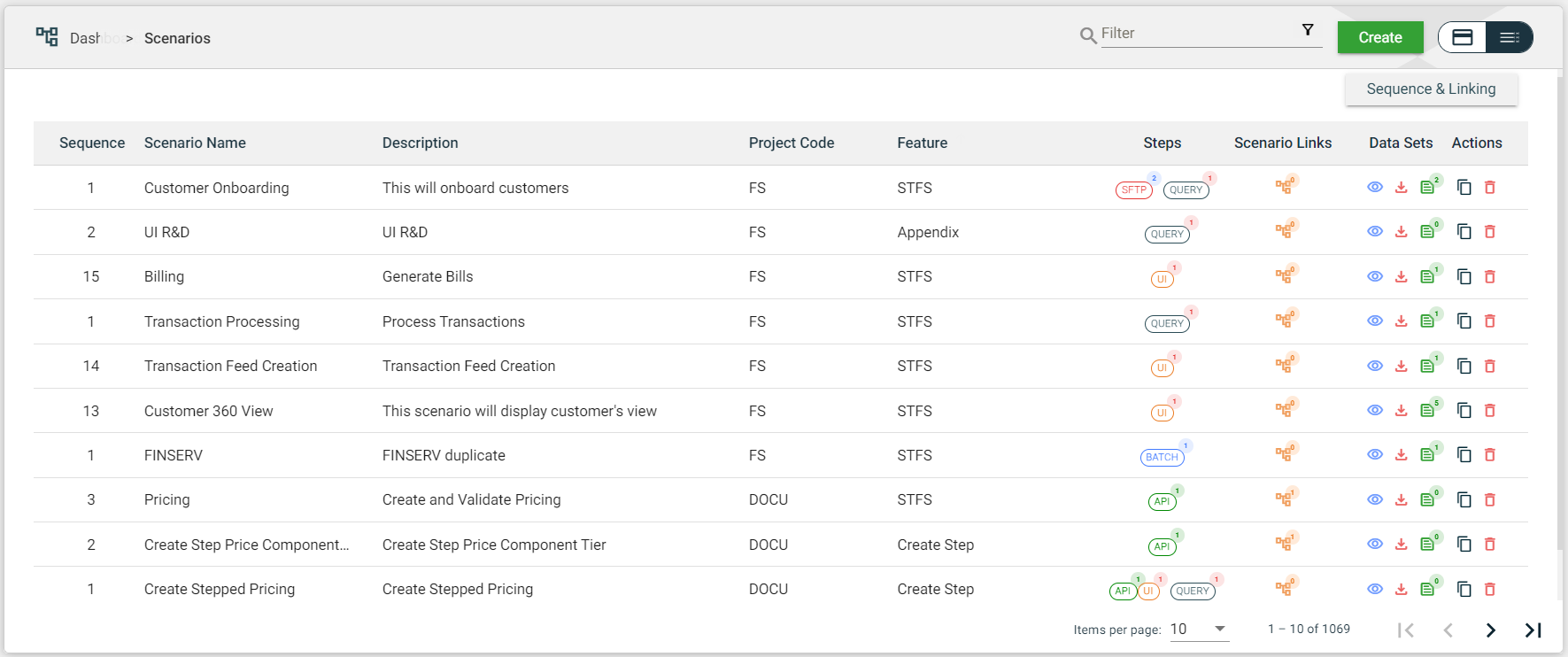
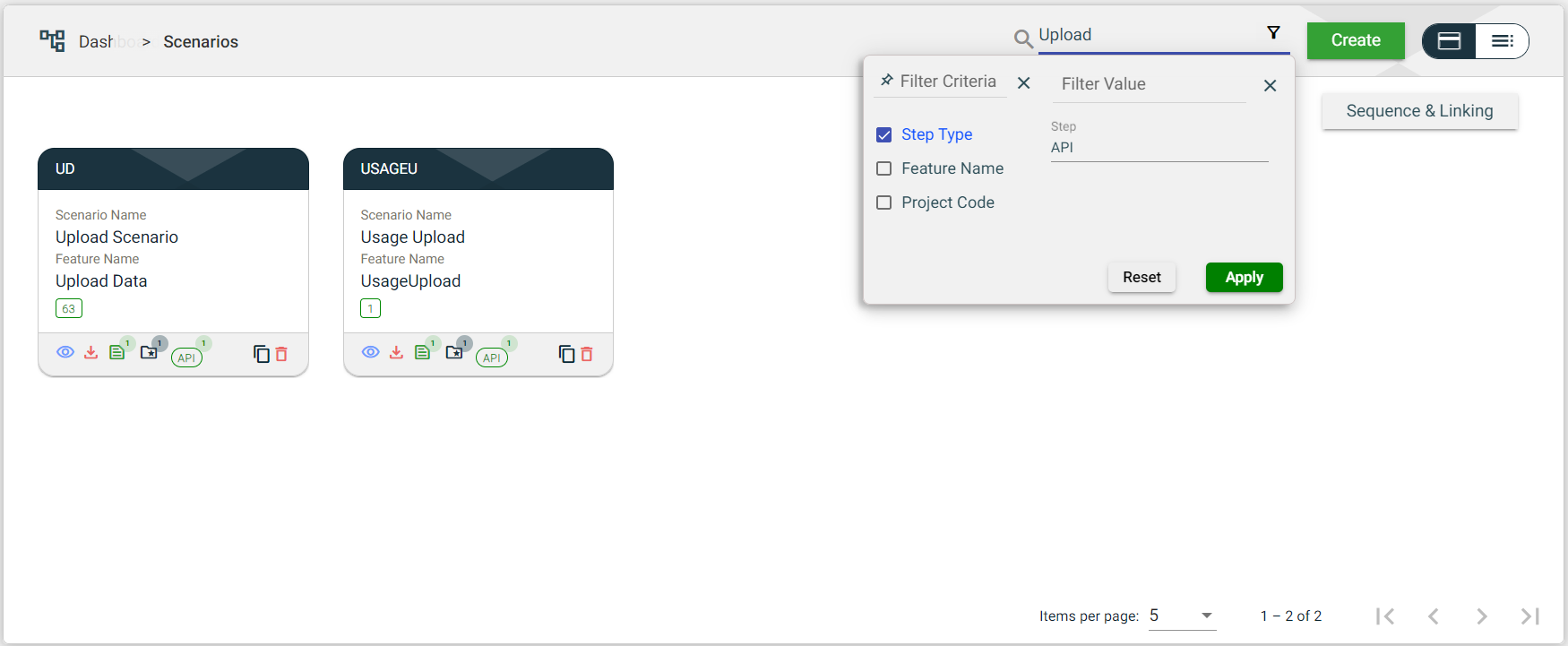
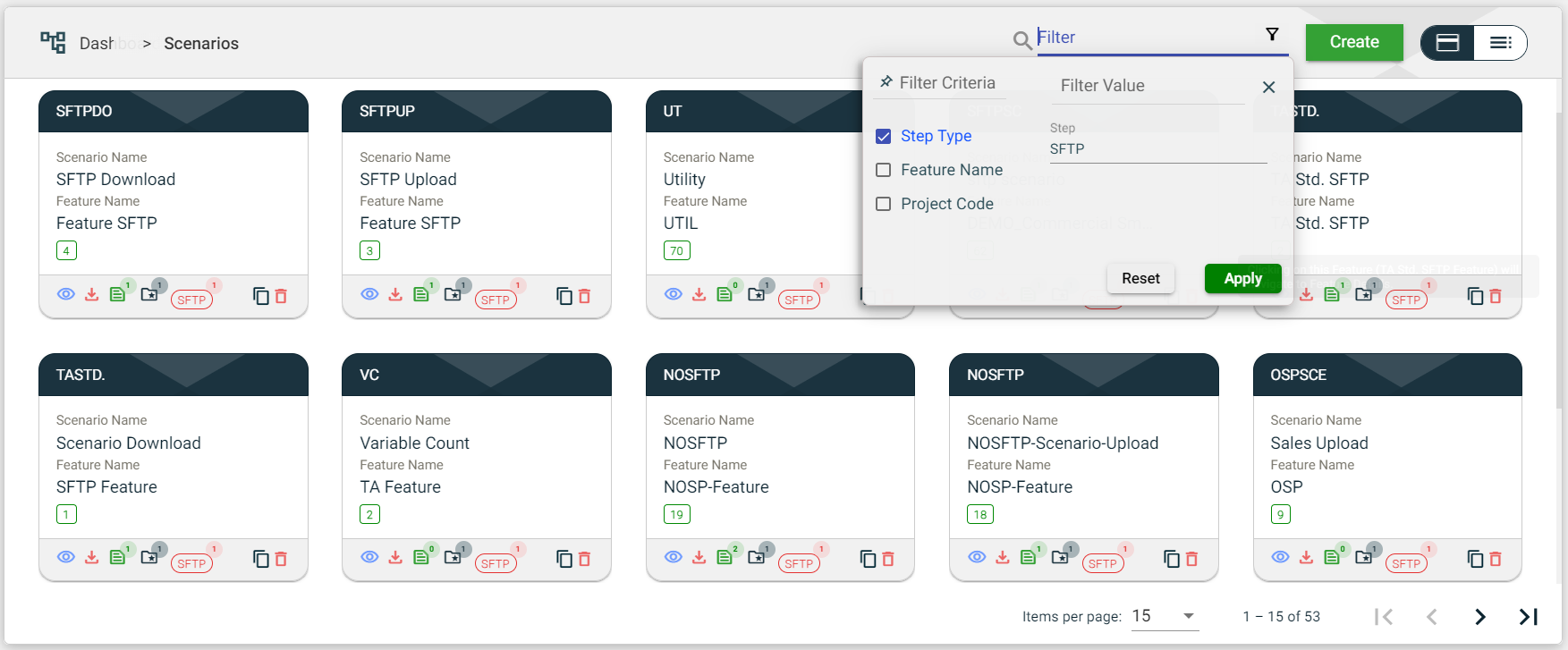
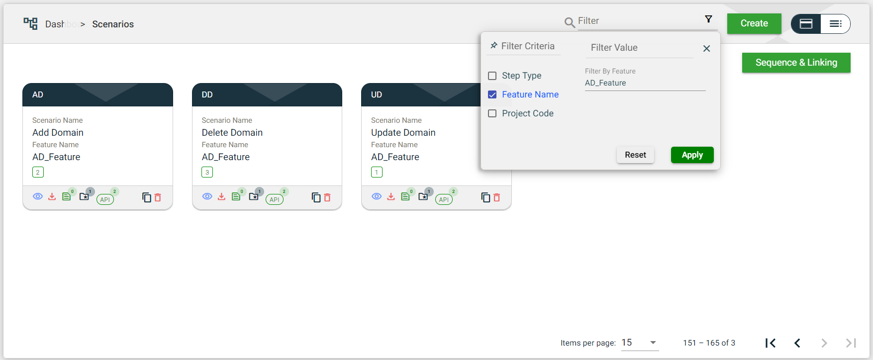
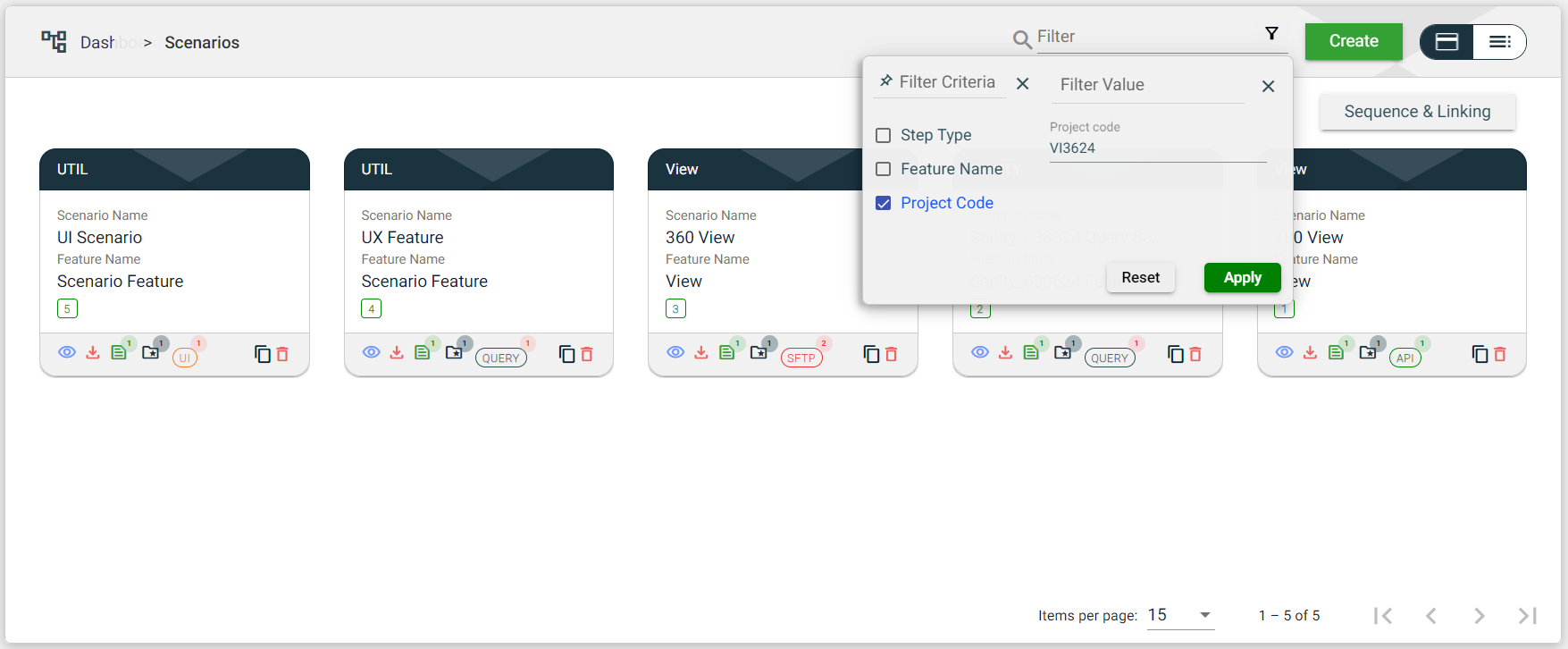
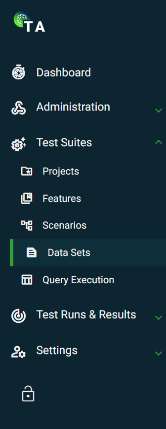
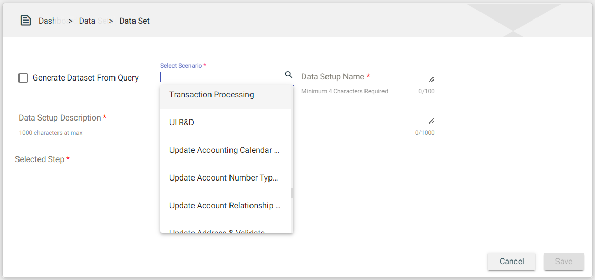
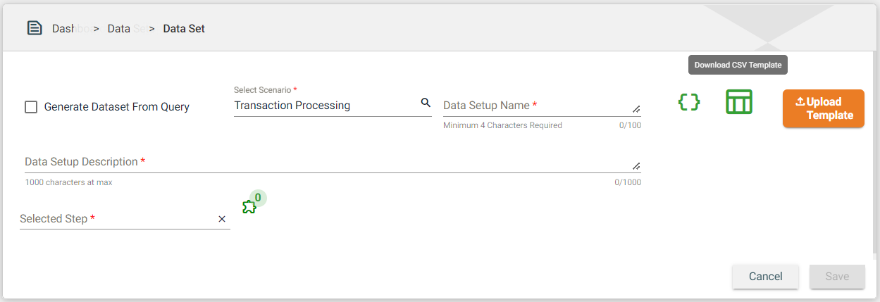
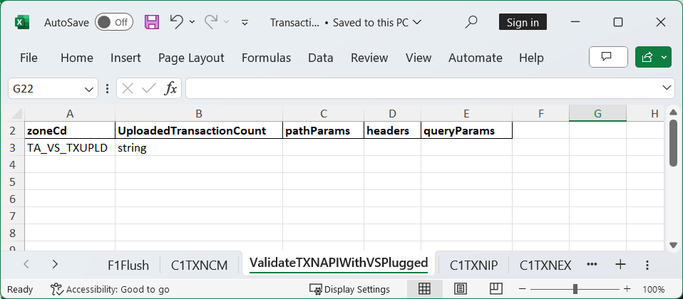
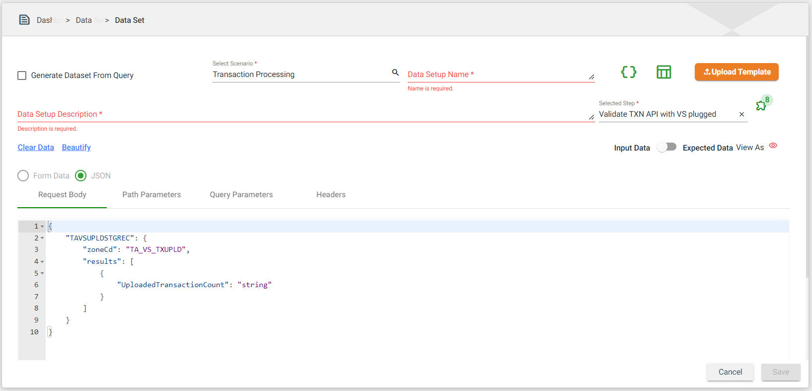
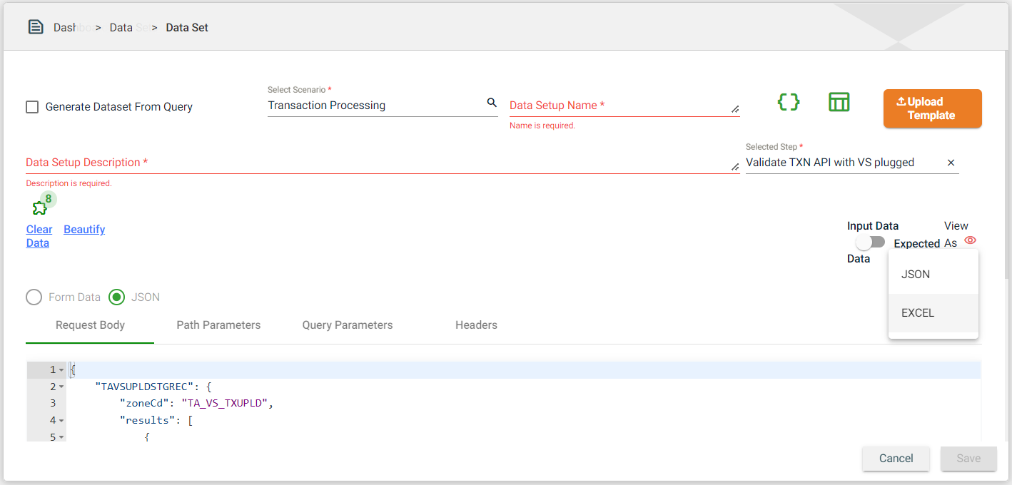
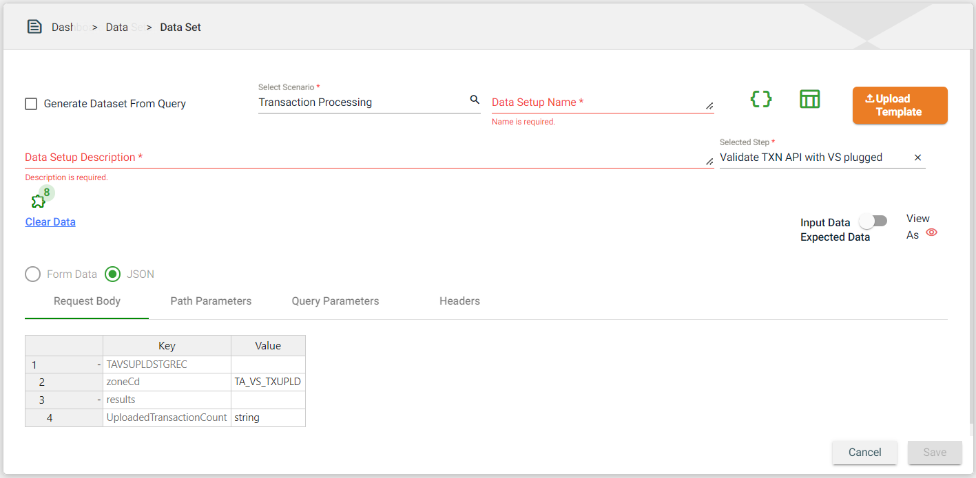
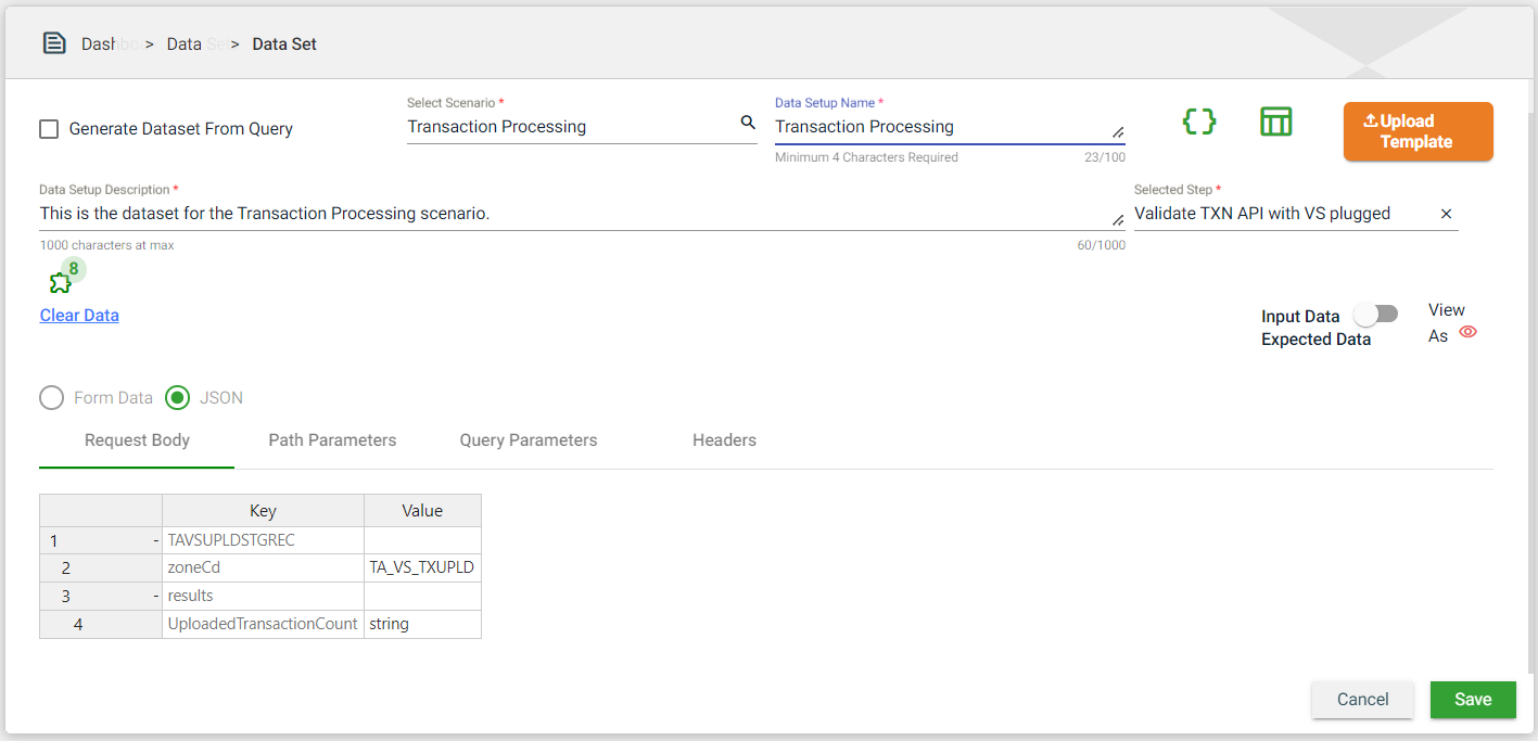
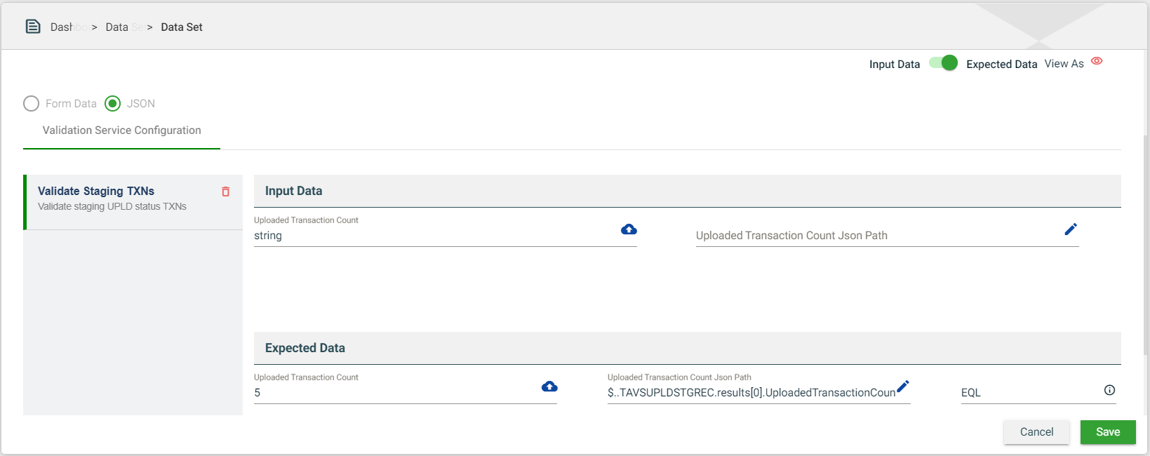
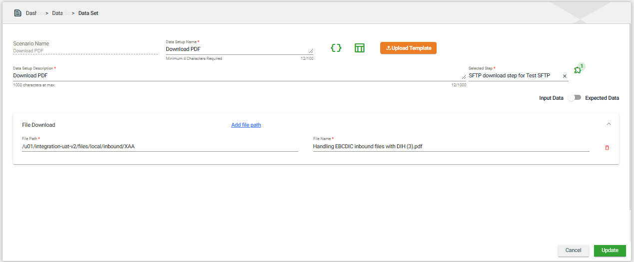
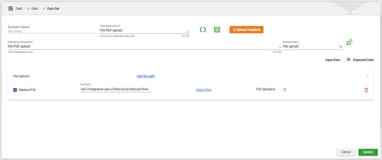
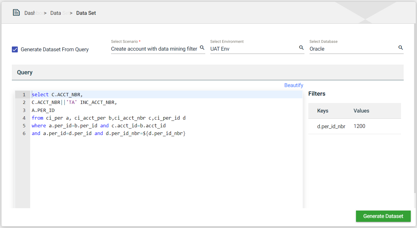
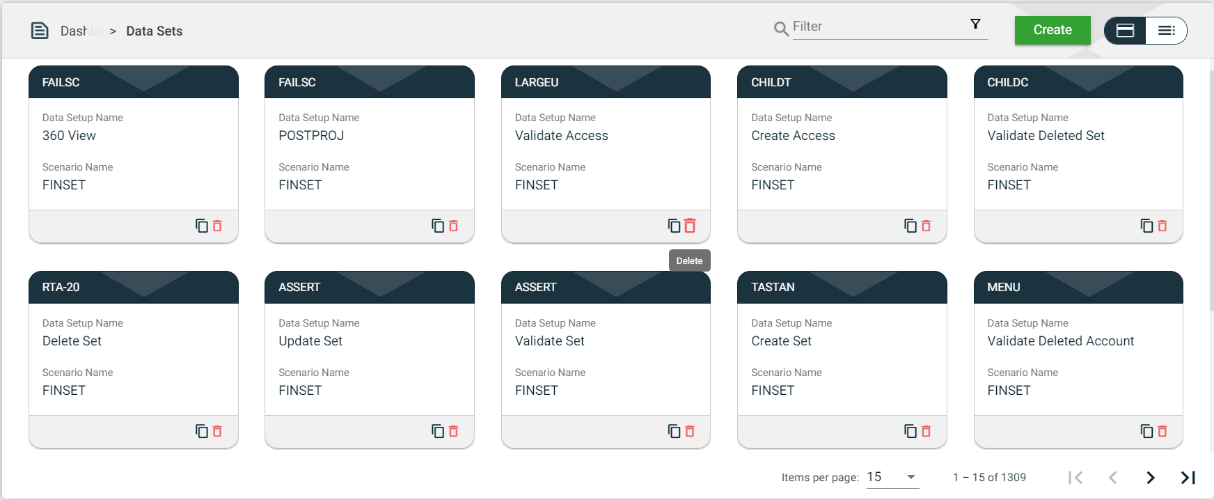
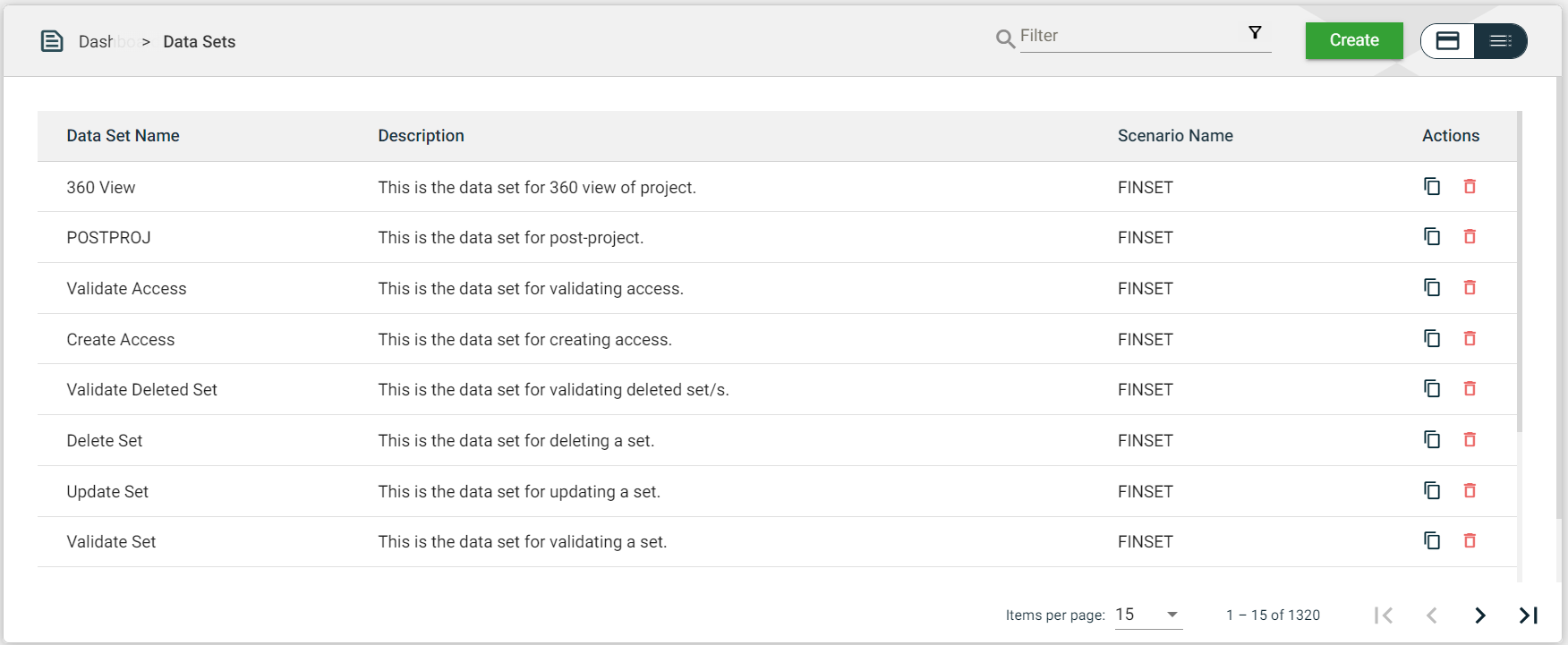
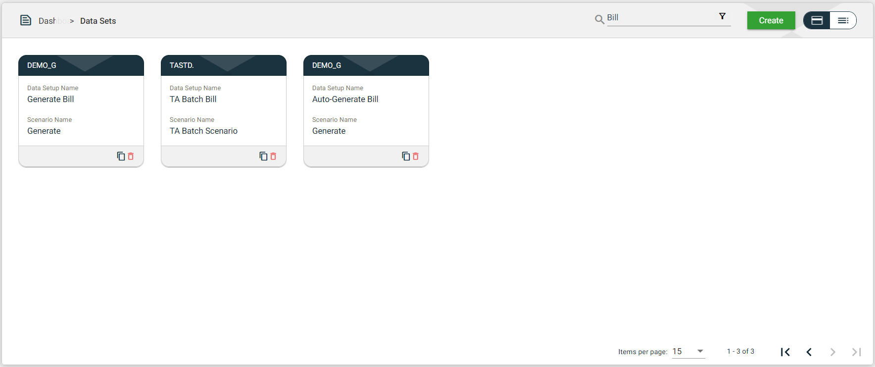
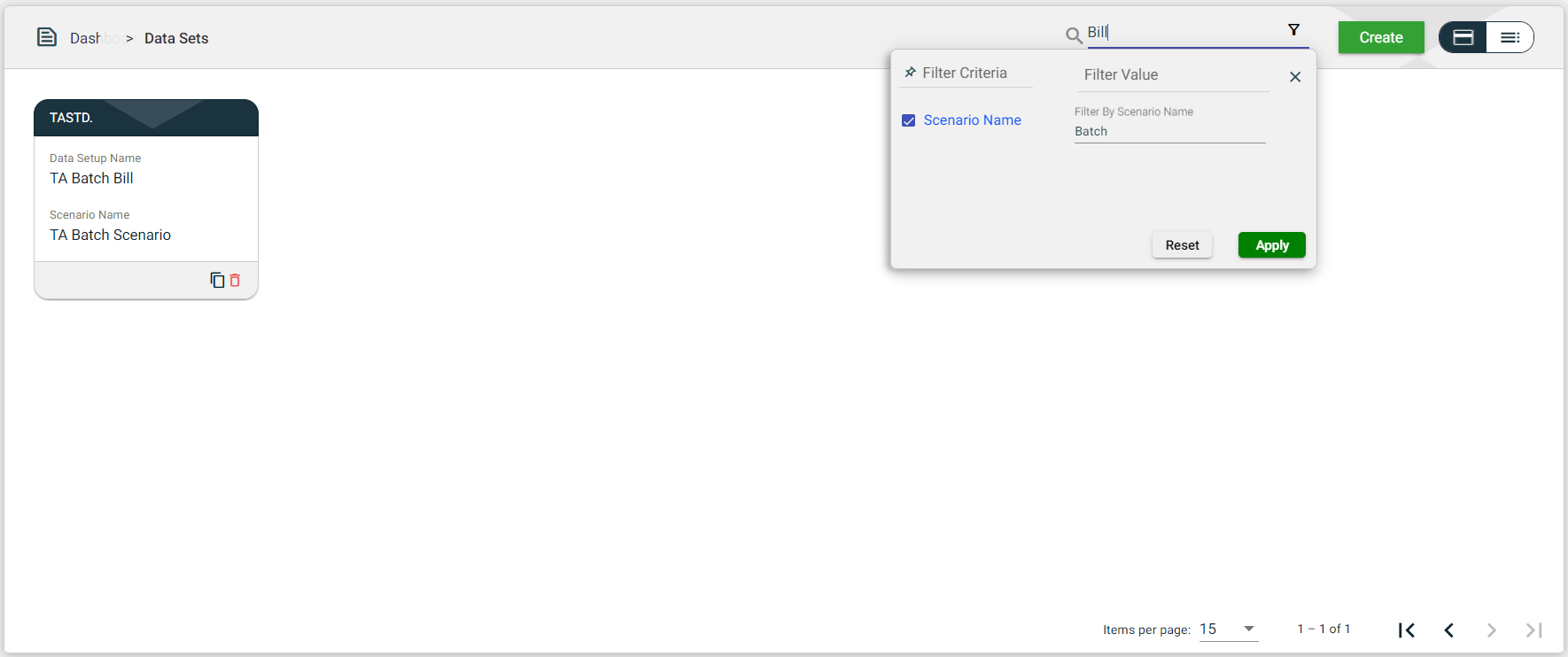
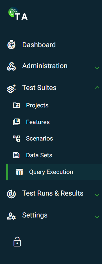
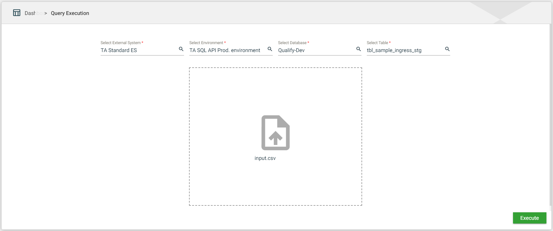
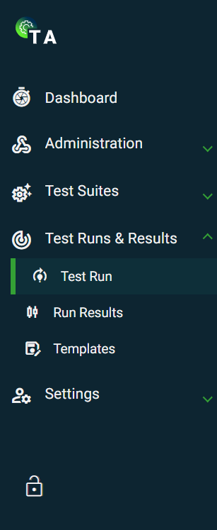
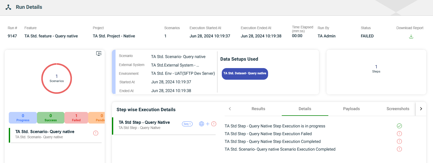
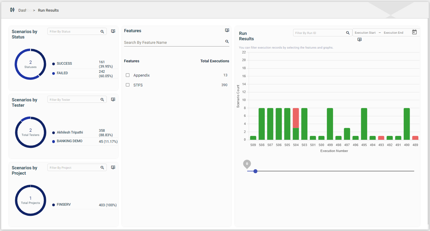
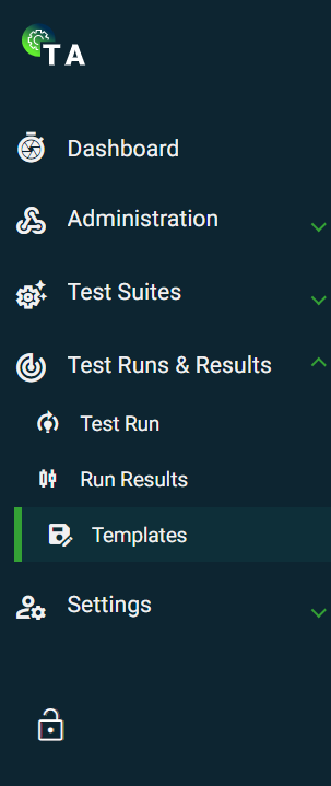
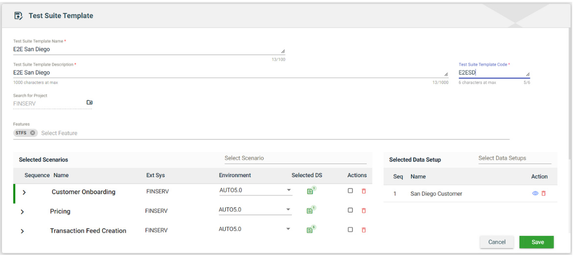
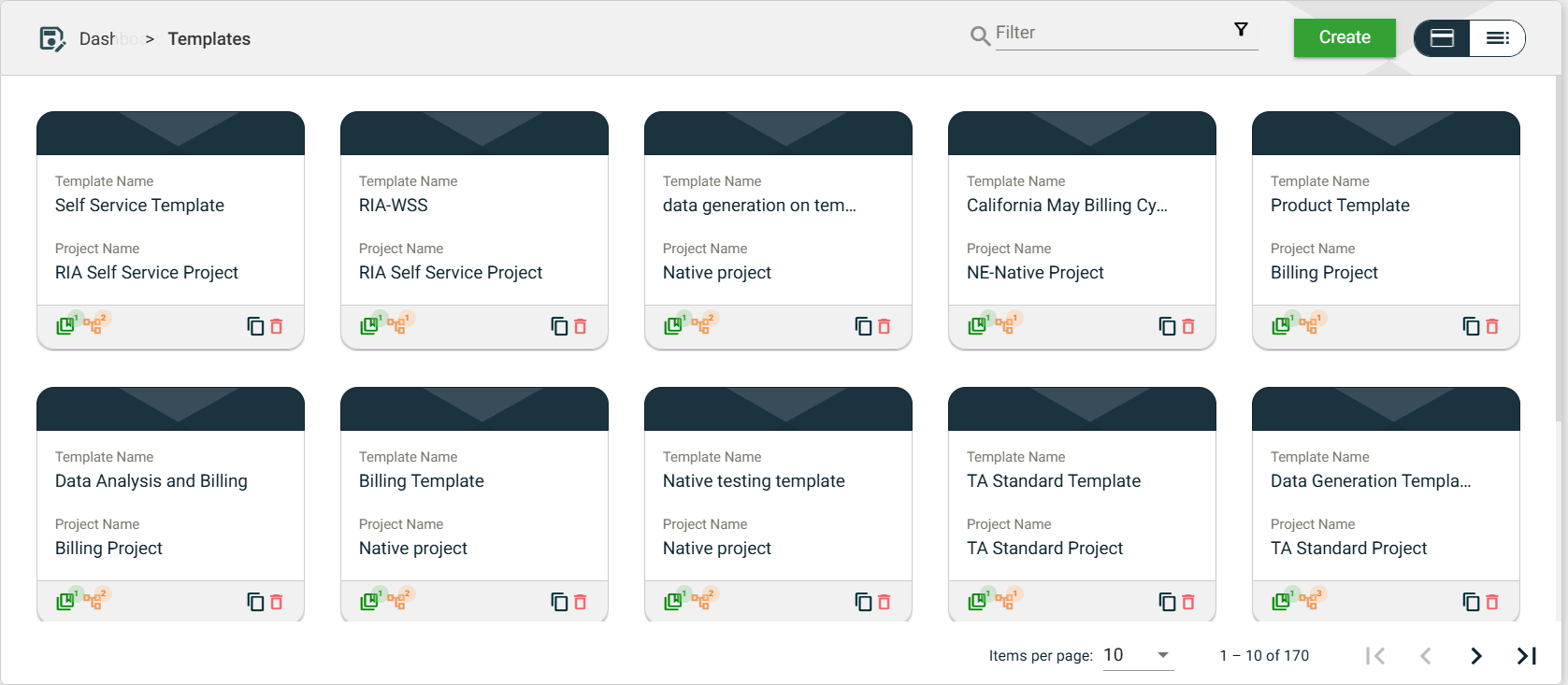
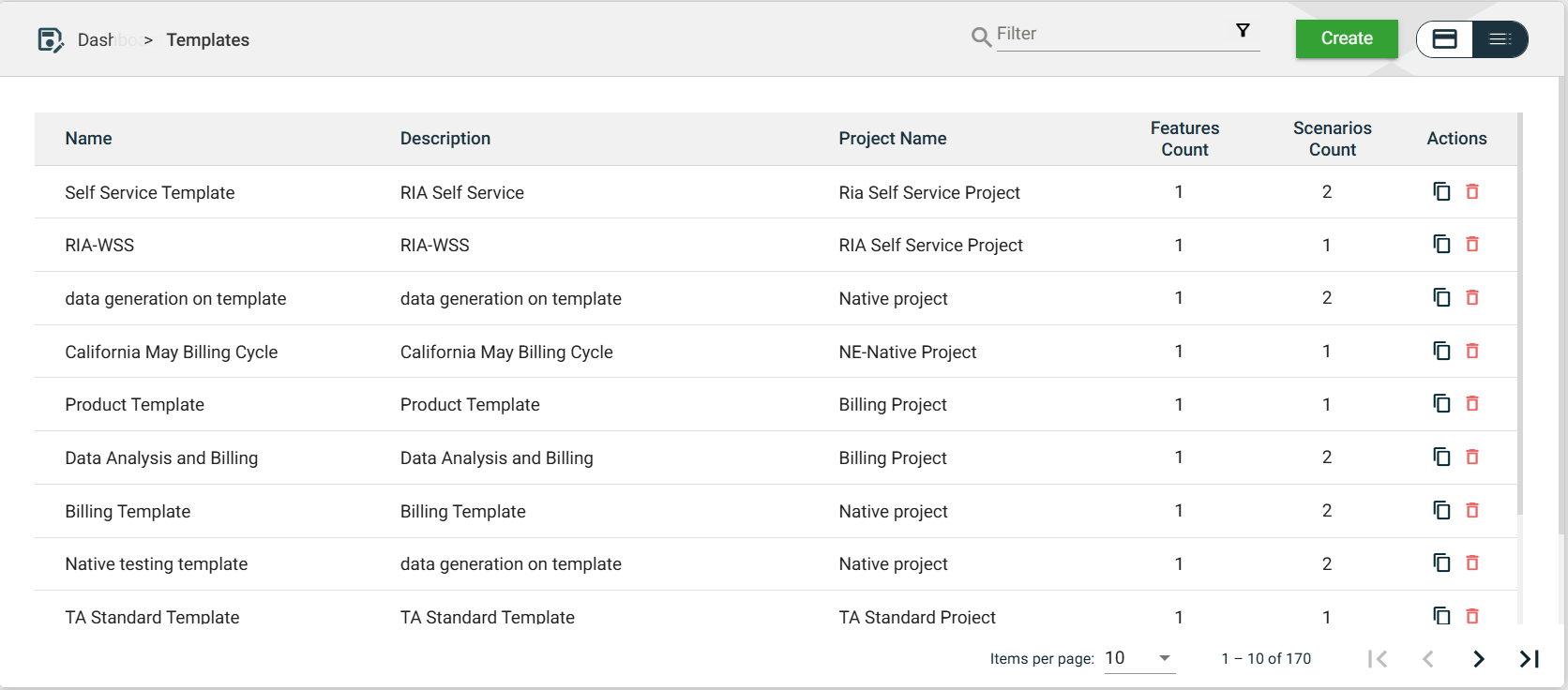
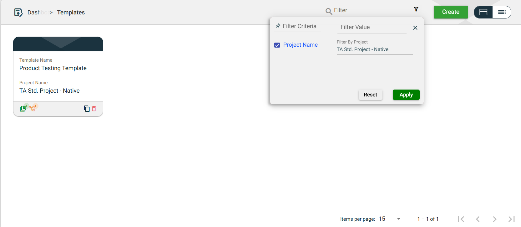
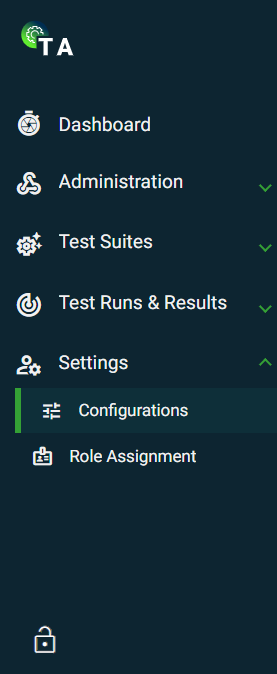
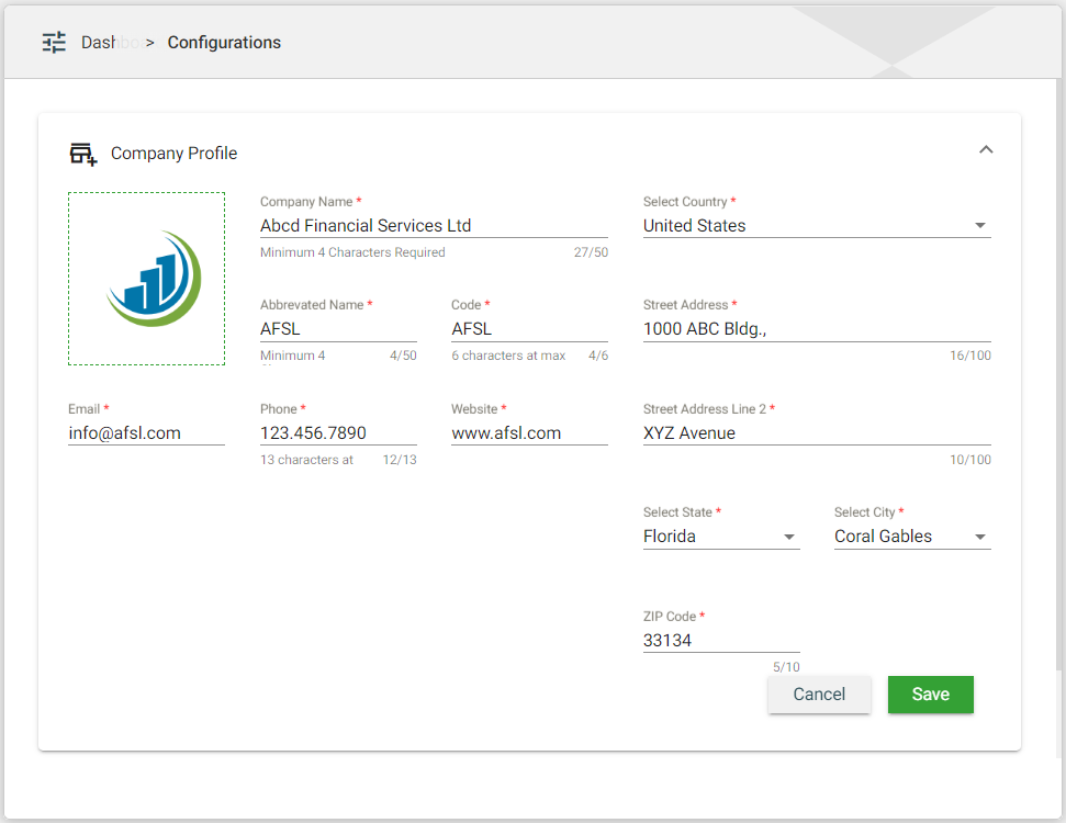
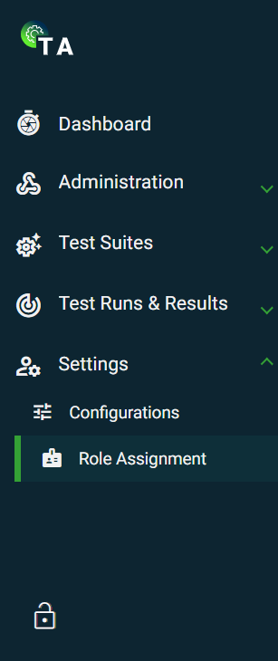
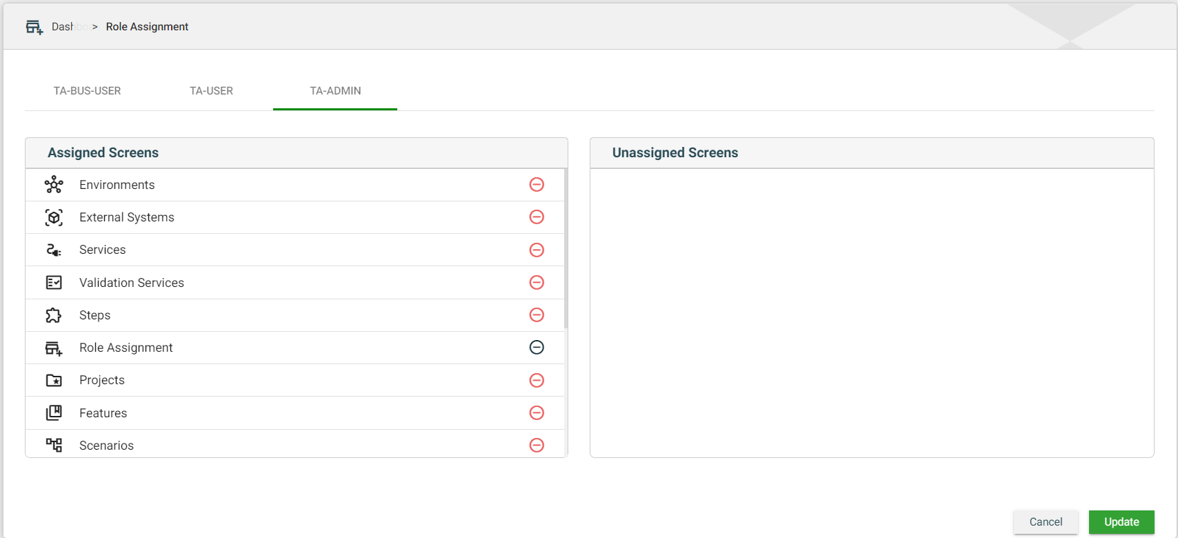
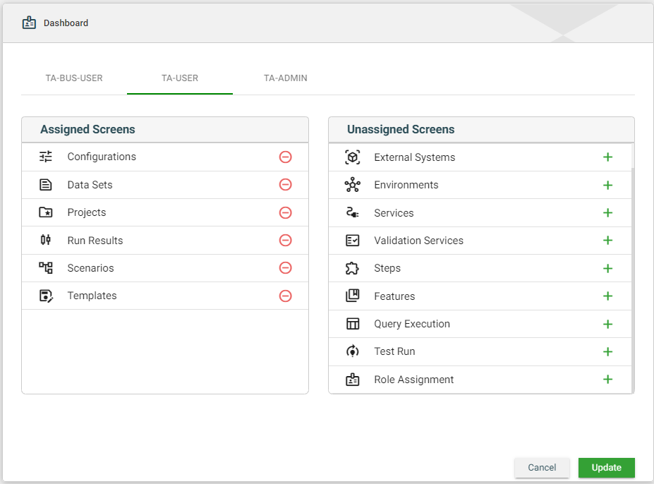
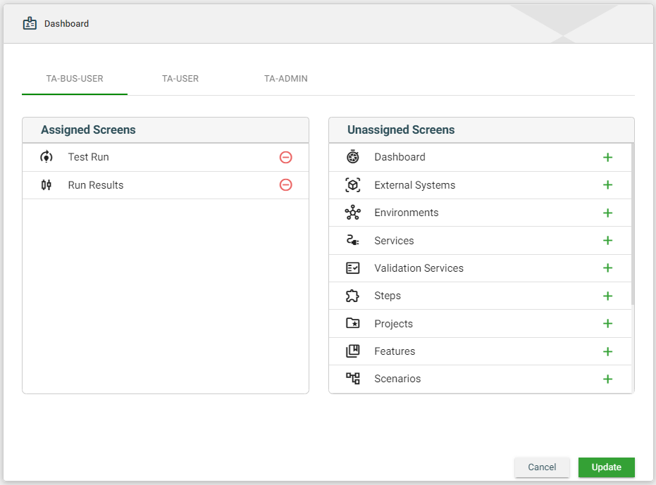
.png)
.png)
.png)